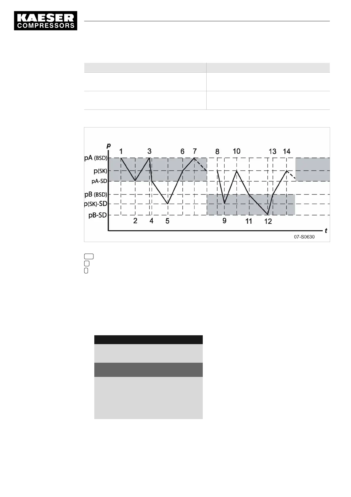
Time period t1–t7: high compressed air demand Time period t8–t14: low compressed air demand
t6:
SK switches to IDLE.
t13:
SK switches to IDLE.
t7:
BSD switches to IDLE.
t14:
BSD switches to IDLE.
Tab. 64 Function diagram
Fig. 35 Function diagram
SD Switching differential
p Pressure
t Time
Setting the system setpoint pressure pA and pB.
Precondition Access level 2 is activated.
1. Select
< Configuration ➙ Pressure control ➙ Pressure settings >
(see Section 7.4.1)
The
< Pressure settings >
menu is displayed.
2. Press «DOWN» repeatedly until
Setpoint pressure pA SP
is displayed as the active line.
8 9 p s i 0 8 : 1 5 1 7 6 ° F
5.2.2 Pressure settings
Menu
Setpoint pressure
pA SP : 123 psi ¦ SD : - 7 psi
Active line with system set-point pressure pA and
switching differential
pB SP : 119 psi ¦ SD : - 7 psi
System pressure setpoint pB and switching differen‐
tial.
·········
System pressure low
< 73 psi ¦ SD : 7 psi
3. Press «Enter» to switch into setting mode.
The
display
for system setpoint pressure
pA
flashes.
4. Use «UP» or «DOWN» to adjust the value.
7 Initial Start-up
7.9 Configuring the machine for master control
116
Service manual Controller
SIGMA CONTROL 2 SCREW FLUID 1.1.3 9_9450 03USE