3-52 Return to Section Topics 4200-900-01 Rev. K / February 2017
Section 3: Common Device Characterization Tests Model 4200-SCS User’s Manual
VdStep double The sweep step size for the Vd sweep, output by the DrainSMU
(defined below).
PulseWidth double The Vgs pulse width (PW). The PW can be 40 ns to 150 ns (10 ns
resolution). Pulses wider than 150 ns will begin to be attenuated by the
capacitor in the 4200-RBT.
PulsePeriod double The pulse period for the Vgs pulse. The period can be set from 100µs to
1 s (10 ns resolution). The period must be set so that the Duty Cycle
(DC) is no more than 0.1%. The period is most easily calculated by
multiplying the largest desired pulse width (PW) by1000. Example: PW
= 150 ns, so Period = 150 us.
AverageNum int The number of pulses to average at each step of the sweep. For best
low signal performance, set AverageNum = 0 for Adaptive Filtering.
GateRange double The voltage measure range for the scope channel measuring the Gate.
Use 0 for scope autoranging, or specify a voltage value for a fixed
range. Valid voltages are 0.050, 0.1, 0.2, 0.5, 1, 2, 5, 10.
DrainRange double The voltage measure range for the scope channel measuring the Drain.
Use 0 for scope autoranging, or specify a voltage value for a fixed
range, where V = I * 50
Ω. Valid voltages are 0.050, 0.1, 0.2, 0.5, 1, 2, 5,
10.
LoadLineCorr int Determines whether to use load line correction to compensate for the
voltage drop caused by the 50 Ω sense resistor used to measure the
drain current (Id).
1 = load line correction active.
0 = no load line correction.
VPUID char * The instrument ID. This should be set to VPU1 for 4200 systems with
the 4200-PIV package.
GateSMU char * The SMU used for the Gate. This can be SMU1 up to the maximum
number of SmUs in the system.
DrainSMU char * The SMU used for the Drain. This can be SMU1 up to the maximum
number of SMUs in the system. This is the SMU that applies the DC
bias to the DUT drain during the sweep.
IdSize
VdMeasSize
VdProgSize
VgSize
VgProgSize
int Set to a value that is at least equal to the number of steps in the sweep
and all five must be the same value.
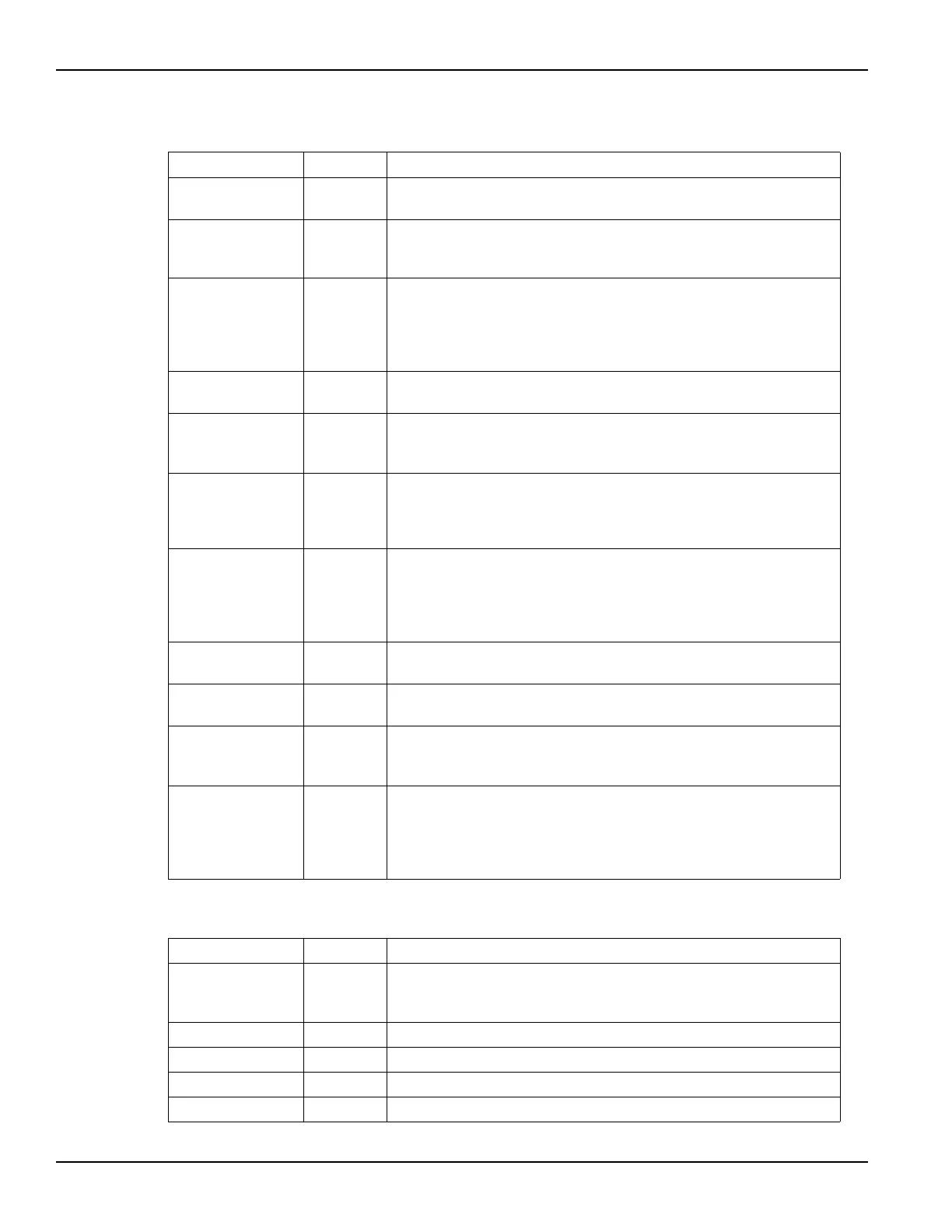
Table 3-8
Outputs for vdsid_pulseiv
Output Type Description
IdArray double * The measured drain current from channel 2 of the scope card. This
current is determined by measuring the voltage drop across the scope
card 50 Ω termination, giving Id = Vd / 50 Ω.
VdMeas double * Array of measured drain voltage values.
VdProg double * Array of programmed drain voltage values.
VgMeas double * The measured gate voltage from channel 1 of the scope card.
VgProg double * Array of programmed gate voltage values.
Table 3-7 (continued)
Inputs for vdsid_pulseiv (continued)
Input Type Description

 Loading...