4200-900-01 Rev. K / February 2017 Return to Section Topics 3-55
Model 4200-SCS User’s Manual Section 3: Common Device Characterization Tests
GateSMURange int The current measurement range to be used for the SMU on the
DUT Gate terminal. Values correspond to the table below. Limited
Auto means that the value given is the minimum measurement
range used, with automatic ranging for larger currents.
1 Full Auto
2 Limited Auto 10 pA
3 Limited Auto 100 pA
4 Limited Auto 1 nA
5 Limited Auto 10 nA
6 Limited Auto 100 nA
7 Limited Auto 1 μA
8 Limited Auto 10 μA
9 Limited Auto 100 μA
10 Limited Auto 1 mA
11 Limited Auto 10 mA
12 Limited Auto 100 mA
DrainSMURange int The current measurement range to be used for the SMU on the
DUT Drain terminal. Values correspond to the table below. Limited
Auto means that the value given is the minimum measurement
range used, with automatic ranging for larger currents.
1 Full Auto
2 Limited Auto 10 pA
3 Limited Auto 100 pA
4 Limited Auto 1 nA
5 Limited Auto 10 nA
6 Limited Auto 100 nA
7 Limited Auto 1 μA
8 Limited Auto 10 μA
9 Limited Auto 100 μA
10 Limited Auto 1 mA
11 Limited Auto 10 mA
12 Limited Auto 100 mA
LoadLineCorr int Determines whether to use load line correction to compensate for
the voltage drop caused by the 50
Ω sense resistor used to
measure the drain current (Id).
1 = load line correction active.
0 = no load line correction.
GateCompliance double The SMU current compliance for the DUT Gate.
DrainCompliance double The SMU current compliance for the DUT Drain.
NPLC double The DC measurement integration time in NPLC (Number of Power
Line cycles).
DCSourceDelay double Time, in seconds, between the DC source and measure for each
sweep point.
DC_vs_Pulse int Determines whether to run a DC and Pulse test or a DC only test or
a Pulse only test. 0 - Pulse Only, 1 - DC Only, 2 - DC and Pulse.
VPUID char * The instrument ID. This should be set to VPU1 for 4200 systems
with a 4200-PIV package.
GateSMU char * The SMU used for the Gate. This can be SMU1 up to the maximum
number of SMUs in the system.
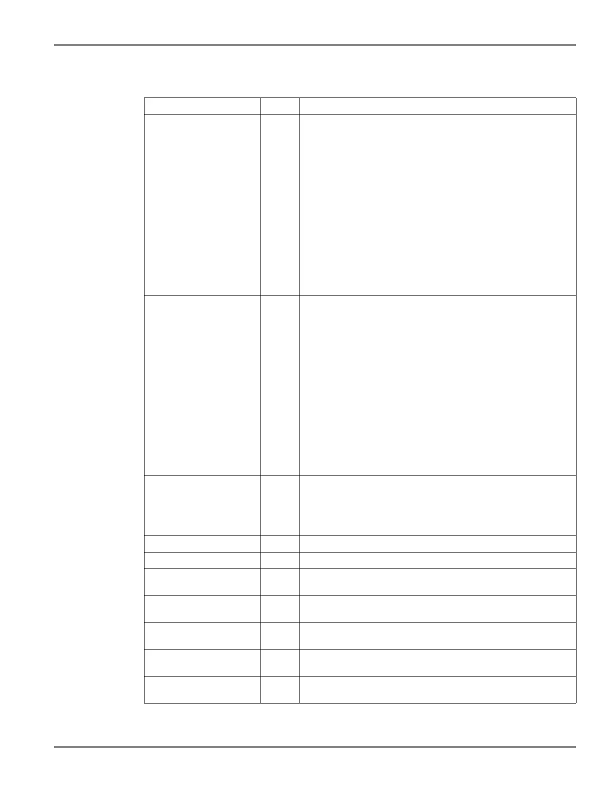
Table 3-10 (continued)
Inputs for VdId_Pulse_DC_Family_pulseiv (continued)
Input Type Description

 Loading...