3-60 Return to Section Topics 4200-900-01 Rev. K / February 2017
Section 3: Common Device Characterization Tests Model 4200-SCS User’s Manual
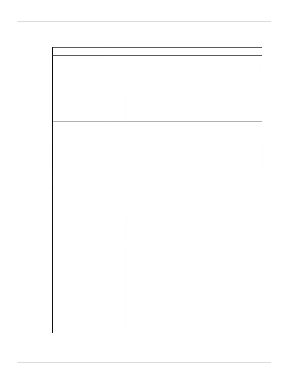
VgStop double The final step value for Vg. For DC only sweeps, VgStop must be
between -200 V to +200 V dependent on the type of SMU and the
current requirements of the DUT. For pulse and pulse and DC
Sweeps, VgStop must be between -5 V to +5 V.
VgStep double The sweep step size for the Vg sweep, output by channel 1 of the
pulse card (VPUID).
Vg_off double The DC bias applied by the GateSMU to put device in the OFF
state. Normally set to 0 V for enhancement FETs (may be non-zero
for depletion FETs). This package does not support a similar
capability for the drain. For full quiescent, or bias, point testing,
review the 4200-PIV-Q specs.
PulseWidth double The Vgs pulse width (PW). The PW can be 40 ns to 250 ns (10 ns
resolution). Pulses wider than 250 ns will begin to be attenuated by
the coupling capacitor in the Remote Bias Tee (4205-RBT).
PulsePeriod double The pulse period for the Vgs pulse. The period can be set from 100
µs to 1 s (10 ns resolution). The period must be set so that the Duty
Cycle (DC) is no more than 0.1%. The period is most easily
calculated by multiplying the largest desired pulse width (PW) by
1000. Example: PW = 150 ns, so Period = 150 µs.
AverageNum int The number of pulses to average at each step of the sweep. For
best low signal performance, set AverageNum = 0 for Adaptive
Filtering.
GateScpRange double The voltage measure range for the scope channel measuring the
Gate. Use 0 for scope autoranging, or specify a voltage value for a
fixed range. Valid voltages are 0.050, 0.1, 0.2, 0.5, 1, 2, 5, 10.
These ranges are Vpp. For example, the 0.5 range covers -
250 to +250 mV.
DrainScpRange double The voltage measure range for the scope channel measuring the
Drain. Use 0 for scope autoranging, or specify a voltage value for a
fixed range, where V = I * 50
Ω. Valid voltages are 0.050, 0.1, 0.2,
0.5, 1, 2, 5, 10. These ranges are Vpp. For example, the 0.5 range
covers -250 to +250 mV.
GateSMURange int The current measurement range to be used for the SMU on the
DUT Gate terminal. Values correspond to the table below. Limited
Auto means that the value given is the minimum measurement
range used, with automatic ranging for larger currents.
1 Full Auto
2 Limited Auto 10 pA
3 Limited Auto 100 pA
4 Limited Auto 1 nA
5 Limited Auto 10 nA
6 Limited Auto 100 nA
7 Limited Auto 1 μA
8 Limited Auto 10 μA
9 Limited Auto 100 μA
10 Limited Auto 1 mA
11 Limited Auto 10 mA
12 Limited Auto 100 mA
Table 3-16 (continued)
Inputs for Vgid_DC_Pulse_pulseiv (continued)
Input Type Description

 Loading...