4200-900-01 Rev. K / February 2017 Return to Section Topics 3-123
Model 4200-SCS User’s Manual Section 3: Common Device Characterization Tests
4. Connect this assembly to the right-most PG2 card, that is, the PG2 card in the lowest
numbered slot. First connect one of the SMA cables to TRIGGER OUT and connect the
SMA tee to TRIGGER IN.
5. Then connect the other SMA cable to TRIGGER IN on the second PG2 card. This second
card is the card to the immediate left of the card in step 4.
NOTE If the FLASH package consists of more than two PG2 cards, continue to connect the
cable and Tees to the adjacent cards. For a system consisting of four PG2 cards,
there should be three SMA tees used to connect the triggering across the four cards.
6. Take one SMA-to-BNC adapter and connect one 5 foot (1.5 m) black BNC cable.
7. Take the cable from step 5 and connect the SMA adapter to CHANNEL 2 of the PG2 in the
left most slot (PG2 in the slot with the highest number).
8. Route BNC cable from step 7 to the switch matrix card Triax input, using a Triax-to-BNC
adapter.
9. Repeat steps 6 through 8 for the other three PG2 pulse channels.
10. Take one black Lemo Triax to three-slot Triax cable and insert the LEMO end into the Force
connection on the left-most SMU in slot four.
11. Route triax from SMU4 to the switch matrix card Triax input.
12. Repeat steps 10-11 for the remaining three SMUs.
13. Use triax cables to route the switch matrix outputs to the array DUT probe manipulators.
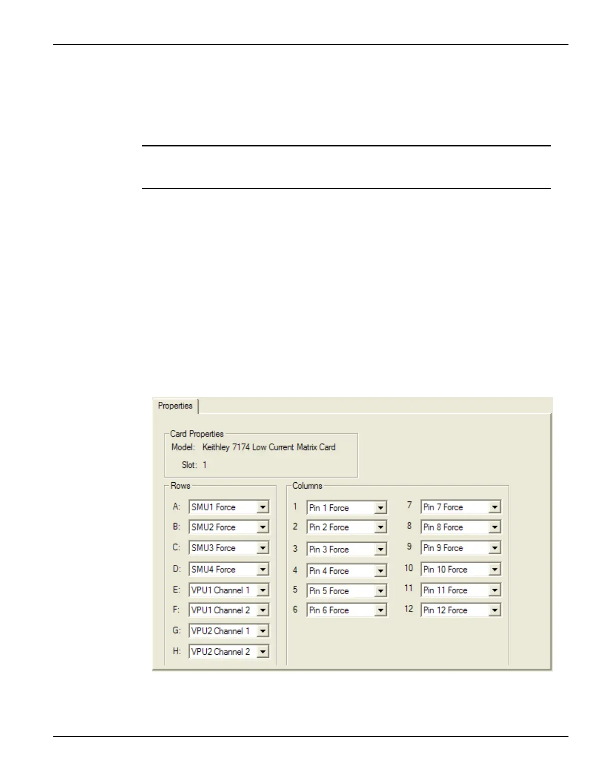
Figure 3-99
KCON Row-Column Card Properties for Flash testing with four SMUs and four VPU pulse
channels

 Loading...