4200-900-01 Rev. K / February 2017 Return to Section Topics 3-135
Model 4200-SCS User’s Manual Section 3: Common Device Characterization Tests
a) PulseVoltages: Use a positive value for a waveform similar to Figure 3-102. If a
negative pulse is required, use a negative voltage value. To put a pulse channel into a
disconnected, or high impedance, state, use -999.
b) PrePulseDelays, TransitionTimes, PulseWidths, PostPulseDelays: The minimum
time is 20 E-9 (20 ns). Number 0 (zero) is not a valid input value. The maximum time is
1 s.
4. Enter the number of pulses into NumPulses. This parameter determines the number of
pulses that will be output each time the test is run.
5. Enter the number of SMUs that are used as Bias Terminals into NumSMUBiasTerminals. An
example of using n SMU as a bias terminal is shown in Figure 3-96. The 4
th
SMU in Figure
3-96 is a dedicated connection to a bit line on the array DUT. During a pulse test, such as
Program or Erase, this SMU would output a DC voltage that would provide power to the
drain terminal of the first column of the array.
6. Enter the SMU IDs for the SMUs used as a bias into SMUBiasTerminals. For the
configuration in Figure 3-96, SMUBiasTerminals = SMU4.
7. Enter the voltages in the array SMUBiasVoltages. These are the voltages for the SMUs
listed in SMUBiasTerminals. The number of non-blank entries in the array must match
NumSMUTerminals.
8. Enter the number of SMUs that are sharing a cable with a pulse channel into
NumSharedSMUs. Sharing means that one pulse and one SMU signal are combined to a
single DUT terminal. Figure 3-96 shows that three pairs of SMU/pulse channels are shared.
Note the SMA tees on each of the top three SMUs that incorporate both a pulse channel
and a SMU signal into a single cable to a DUT terminal. Supplying the shared SMU
information allows the software to open the SMU relay during the pulse output, which is
necessary to permit good pulse fidelity. If a switch matrix is used in the configuration (see
Figure 3-97), then use NumSharedSMUs = 0.
9. Enter the SMU IDs for the SMUs sharing a cable with a pulse channel into SharedSMUs.
For the configuration in Figure 3-96, SharedSMUs = SMU1,SMU2,SMU3. There are no
spaces allowed in the SharedSMUs string.
10. Press the green triangle Run button to output the pulses.
11. Check the Data tab in the Sheet control. The single_pulse_flash value should be 0,
indicating that there were no errors. No measurements are taken in this test, so there is no
data to graph.
12. If single_pulse_flash is non-zero, pulses are not being output, or there are error messages
in the Project Messages pane, see Troubleshooting section.
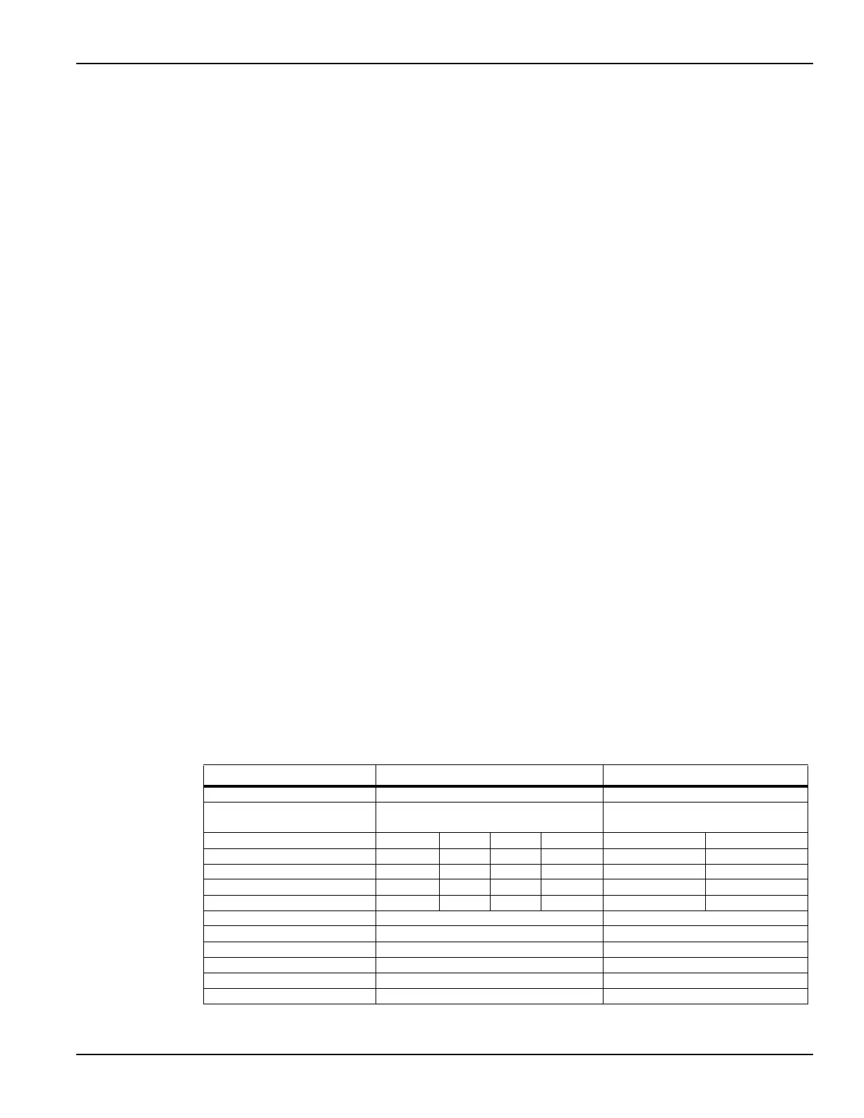
Table 3-31
Parameter values for Program or Erase UTM for 4 or 2 channel configurations
Parameter Value for 4 channel test Value for 2 channel test
NumPulseTerminals 4 2
PulseTerminals VPU1CH1, VPU1CH2, VPU2CH1,
VPU2CH2
VPU1CH1, VPU1CH2
PulseVoltages 0 7 0 0 0 7
PrePulseDelays 1 E-6 1 E-6 1 E-6 1 E-6 1 E-6 1 E-6
TransitionTimes 3 E-7 3 E-7 3 E-7 3 E-7 3 E-7 3 E-7
PulseWidths 5 E-6 5 E-6 5 E-6 5 E-6 5 E-6 5 E-6
PostPulseDelays 2 E-6 2 E-6 2 E-6 2 E-6 2 E-6 2 E-6
NumPulses 1 1
NumSMUBiasTerminals 0 0
SMUBiasTerminals
SMUBiasVoltages
NumSharedSMUs 4 2
SharedSMUs SMU1,SMU2,SMU3,SMU4 SMU1,SMU2

 Loading...