4200-900-01 Rev. K / February 2017 Return to Section Topics 4-23
Model 4200-SCS User Manual Section 4: How to Control Other Instruments with the Model 4200-SCS
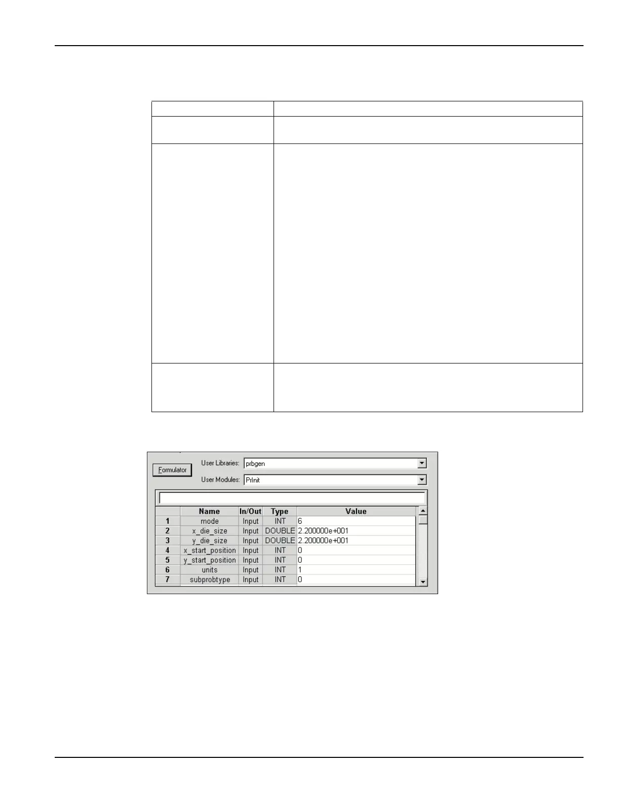
Figure 4-30
prober-init
Tab l e 4- 5
probesubsites test descriptions
probesubsites Project Test Description
InitializationSteps
prober-init
Initializes the prober driver (see Figure 4-30).
Subsite1
4terminal-n-fet
connect
vds-id-1x
3terminal-npn-bjt
connect
vce-ic-1x
probe-ss-move
Subsite2
4terminal-n-fet
connect
vds-id-2x
3terminal-npn-bjt
connect
vce-ic-2x
probe-ss-move
Connects the SMUs to the probes for the N-channel MOSFET (see
Figure 4-31).
Generates a family of curves (I
D
vs. V
D
) for the MOSFET.
Connects the SMUs to the probes for the NPN transistor (see Figure 4-32).
Generates a collector family of curves (I
C
vs. V
C
) for the transistor.
Moves the prober to next subsite.
Connects the SMUs to the probes for the N-channel MOSFET (see
Figure 4-31).
Generates a family of curves (I
D
vs. V
D
) for the MOSFET.
Connects the SMUs to the probes for the NPN transistor (see Figure 4-32).
Generates a collector family of curves (I
C
vs. V
C
) for the transistor.
Moves the prober to the first subsite of the next site.
TerminationSteps
prober-separate
prober-prompt
The following steps occur after all three sites are tested:
Separates the prober pins from the wafer (see Figure 4-33).
Displays a pop-up window indicating that testing is finished (see
Figure 4-34).
Line 1: Parameter value 6 selects the Learn control mode. Assumes that the probe list
is maintained by the prober controller software.
Lines 2 and 3: These parameters (along with the units setting in Line 6) input a die size of
22 mm x 22 mm.
Lines 4 and 5: These parameters input the initial prober position as the 0, 0 coordinates.
Line 6: Parameter value 1 sets units for die size (lines 2 and 3) to metric.
Line 7: (not used)

 Loading...