215184 112 Revision A
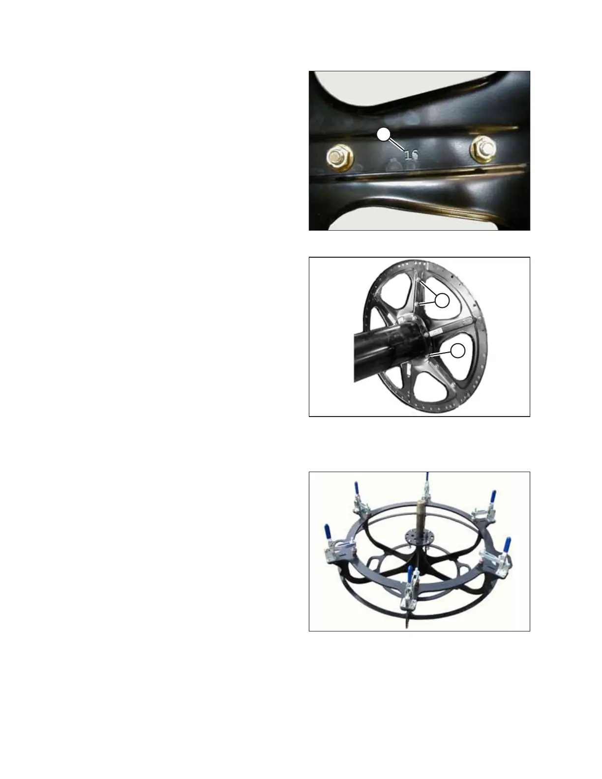
Figure 3.234: 16-Gauge Discs
5. Position 16-gauge sections (number [A] stamped on each
disc section) at the end of the reel tube with the stub shaft.
Figure 3.235: Disc Hardware Locations
6. Install 16-gauge discs with 1/2 x 1.0 in. long Torx
®
bolts and
nuts (A) and 1/2 x 3/4 in. long Torx
®
bolts and nuts (B)
(provided in the hardware bag labelled B). Longer bolts (A)
are installed at the reel center tube flange locations. Line
up seams with previously installed disc and ensure flanges
on disc sections face inboard.
7. Hand-tighten hardware.
8. Install the 18-gauge discs at the center location with
1/2 x 1.0 in. long Torx
®
bolts and nuts and 1/2 x 3/4 in. long
Torx
®
bolts and nuts (provided in the hardware bag labelled
B). The longer bolts are installed at the reel center tube
flange locations. Ensure flanges on discs face the same
direction as flanges on the outer disc.
9. Hand-tighten hardware.
Aligning Solid Disc
Figure 3.236: Jig
IMPORTANT:
A jig is required to ensure solid discs are aligned properly and
assembled straightly. The jig is included with the first shipment of
headers to each setup location.
ASSEMBLING THE HEADER AND FLOAT MODULE