215184 314 Revision A
Figure 9.16: Optional Two-Sensor Kit – Right Sensor
10. Using a voltmeter, measure the voltage between the
ground (Pin 2) and signal (Pin 3) wires of AHHC sensor (A)
at the back of the side frame. Ensure it is at the low voltage
limit for the combine. For voltage limit chart, refer to
Table 9.1, page 307.
NOTE:
The wiring harness connector must be attached to the
sensor. Do NOT disconnect it.
11. If the sensor voltage is not within the low and high limits,
or if the range between the low and high limits is
insufficient, adjust the voltage limits. For instructions, refer
to Adjusting Voltage Limits – Two-Sensor System, page 316.
12. Repeat at the opposite side.
Adjusting Voltage Limits – One-Sensor System
Follow this procedure if you have checked the voltage range (either manually or from the cab) and found that the sensor
voltage is not within the low and high limits, or that the range between the low and high limits is insufficient.
WARNING
To avoid injury or death from unexpected start-up of machine, always stop the engine and remove the key from the
ignition before leaving the operator’s seat for any reason.
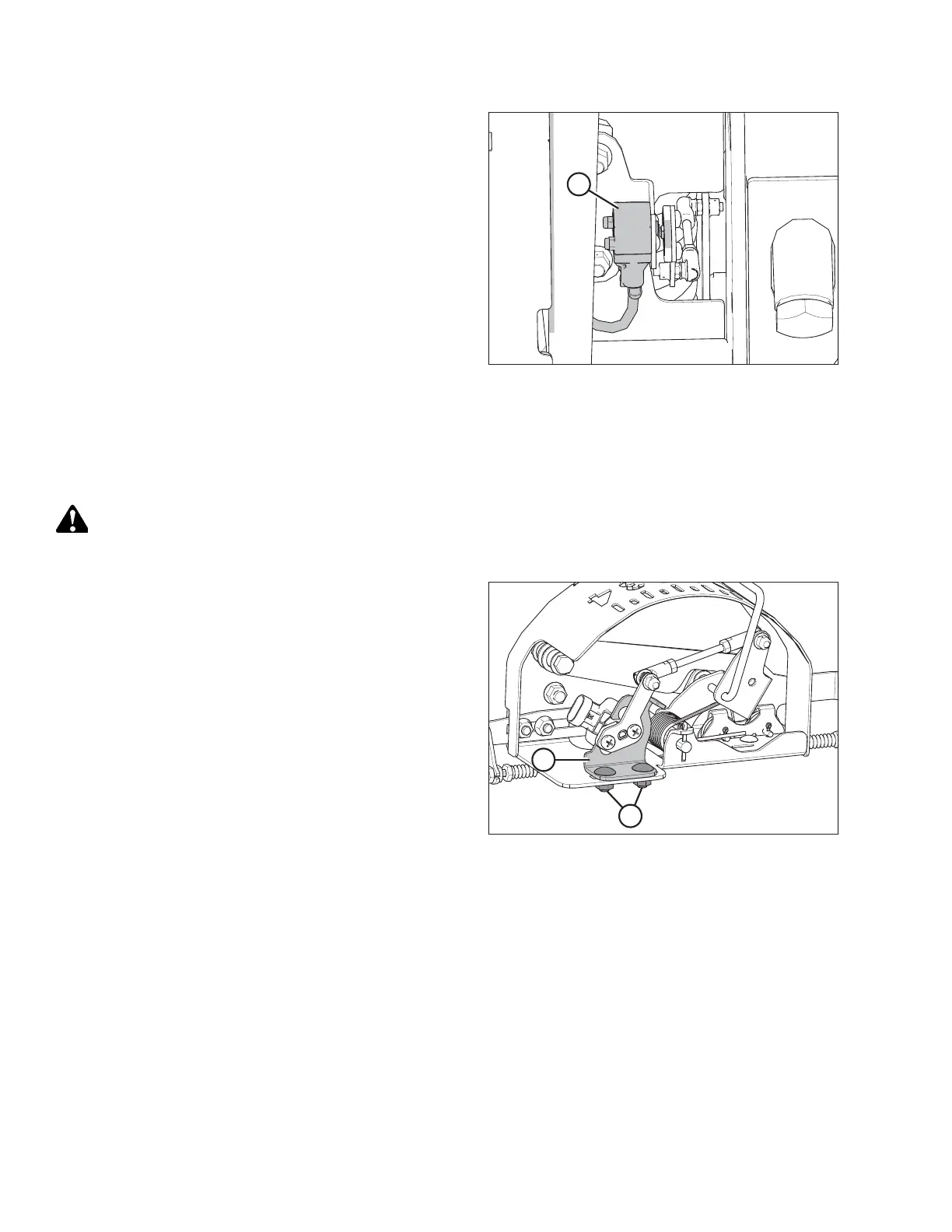
Figure 9.17: AHHC Sensor Assembly
1. Follow these steps to adjust the high voltage limit:
a. Extend guard angle fully; the header angle indicator
should be at D.
b. Position header 152–254 mm (6–10 in.) above the
ground; the float indicator should be at 0.
c. Check the high voltage limit using the combine display
or a voltmeter. For voltage limit chart, refer to
Table 9.1, page 307.
d. Loosen sensor-mounting nuts (A).
e. Slide sensor support (B) to the right to increase high
voltage limit or to the left to decrease it.
f. Tighten sensor-mounting nuts (A).
SETTING UP AUTO HEADER HEIGHT CONTROL