215184 318 Revision A
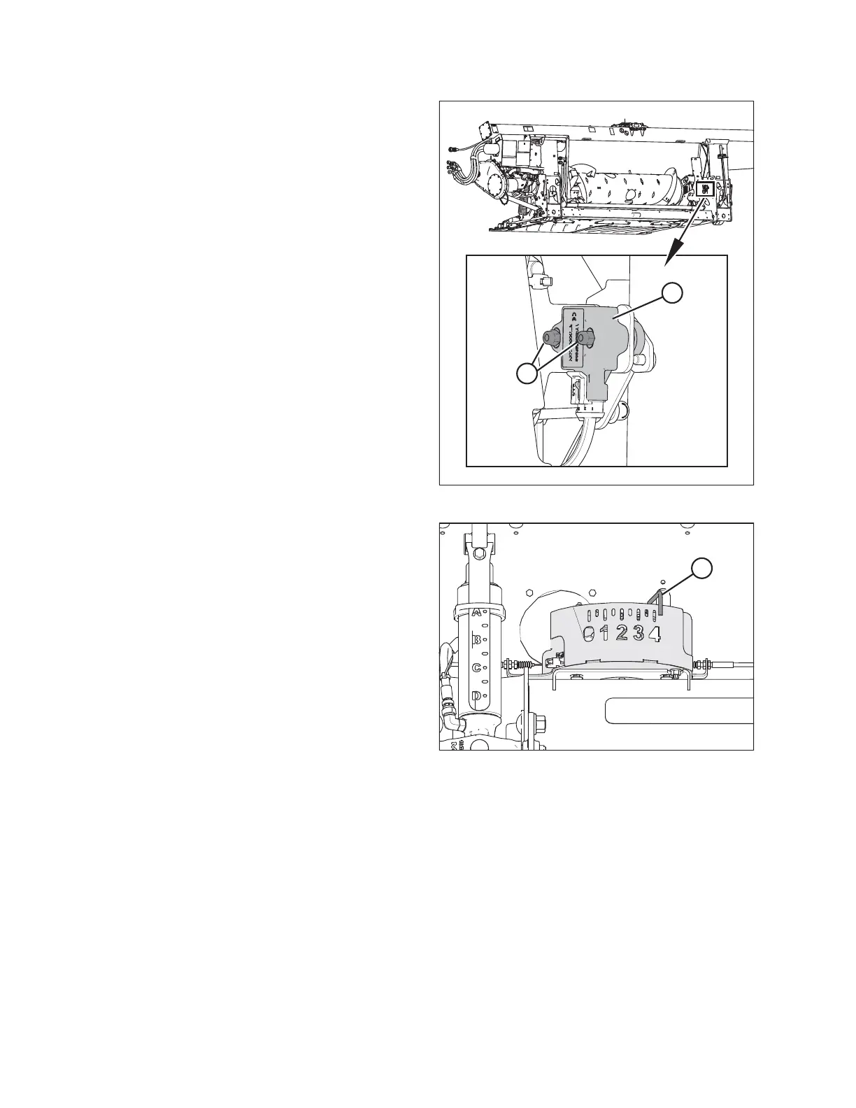
Figure 9.21: Optional Two-Sensor Kit – Right Sensor
10. Loosen sensor mounting nuts (A).
11. Rotate sensor (B) clockwise to lower the voltage. Rotate
sensor counterclockwise to raise the voltage.
12. Check that the right sensor is at the correct high
voltage limit according to Table 9.1, page 307.
13. Tighten sensor mounting nuts (A).
Figure 9.22: Float Indicator Box
14. Fully lower the header; float indicator (A) should be at 4.
15. Check that both sensors are at the correct low voltage limit
according to Table 9.1, page 307.
9.1.4 AGCO IDEAL
™™
Series Combines
Setting up the Header – AGCO IDEAL
™
Series
NOTE:
Up-to-date images of the AGCO IDEAL
™
Series combine display were not available at time of publishing. For instructions,
refer to the combine operator’s manual for updates.
SETTING UP AUTO HEADER HEIGHT CONTROL