215184 317 Revision A
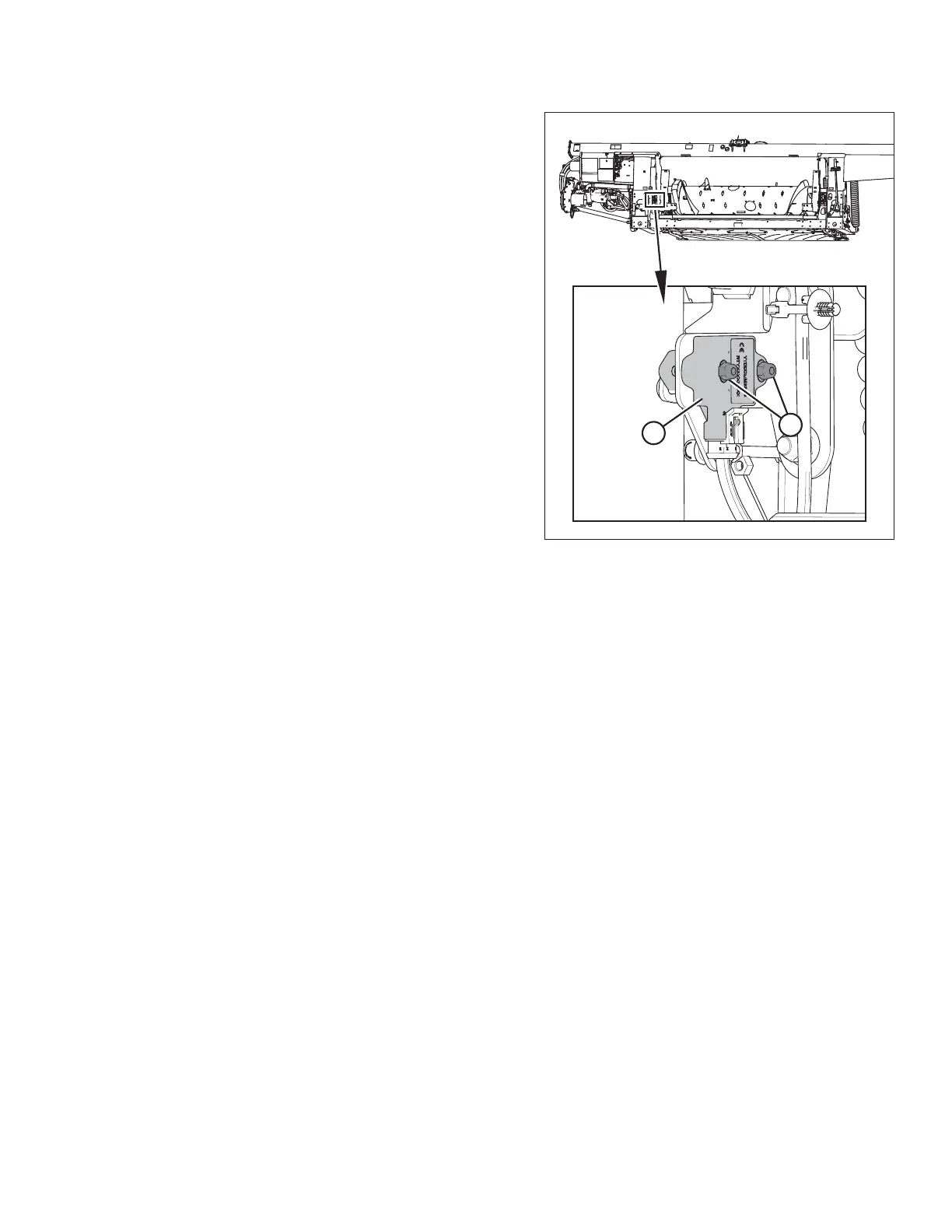
Figure 9.20: Optional Two-Sensor Kit – Left Sensor
4. Loosen sensor-mounting nuts (A).
5. Check that the left sensor is at the correct high voltage limit
according to Table 9.1, page 307.
6. Rotate sensor (B) counterclockwise to lower the voltage.
Rotate sensor clockwise to raise the voltage.
7. Tighten sensor-mounting nuts (A).
Follow these steps to adjust the right sensor voltage:
8. Extend guard angle fully; the header angle indicator should be at D.
9. Position header 150–254 mm (6–10 in.) above the ground; the float indicator should be at 0.
SETTING UP AUTO HEADER HEIGHT CONTROL