215184 198 Revision A
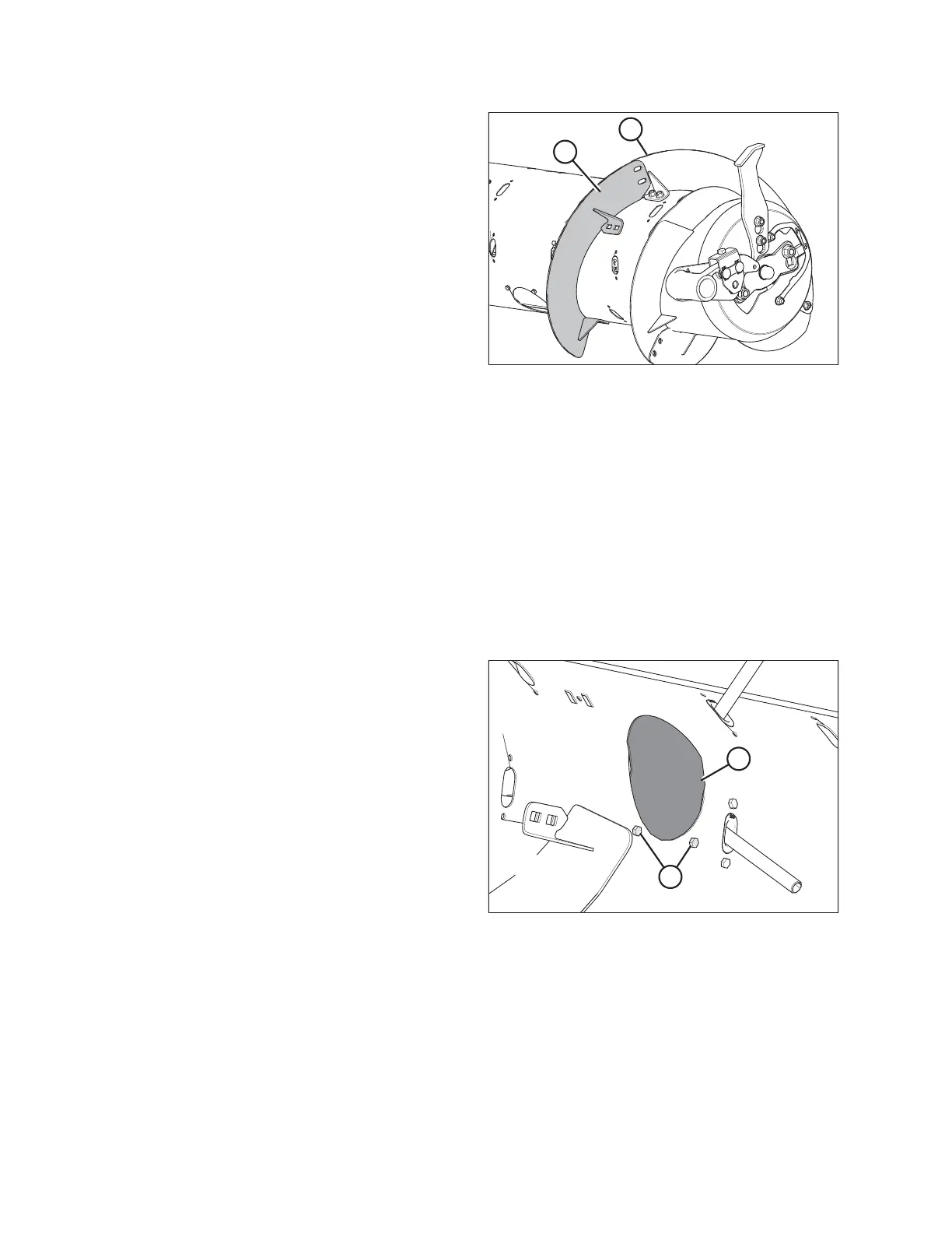
Figure 6.55: Flighting on Right Side of Auger
15. Place flighting (A) outboard of existing flighting (B) on the
right side of the auger, as shown.
16. Repeat Step 3, page 196 to Step 13, page 197 for both
flightings on the right side of the auger.
17. On both sides of the auger, install flighting slot plugs
(MD #213084) in the flighting mounting locations and
secure with M6 bolts (MD #252703) and tee nuts
(MD #197263).
18. Torque all nuts and bolts to 47 Nm (35 lbf·ft) to eliminate
deflection on flighting, then torque nuts and bolts again to
58–64 Nm (43–47 lbf·ft).
NOTE:
Flighting performs best when no gaps are present. If
desired, use silicone sealant to fill the gaps.
19. Add or remove auger fingers as necessary to optimize feeding for your combine and crop conditions. For instructions,
refer to 6.2.10 Installing Feed Auger Fingers, page 198 or 6.2.11 Removing Feed Auger Fingers, page 200.
20. If not adding or removing auger fingers, reinstall all access covers and secure with bolts. Coat bolts with medium-
strength threadlocker (Loctite
®
243 or equivalent) and torque to 9 Nm (80 lbf∙in).
6.2.10 Installing Feed Auger Fingers
NOTE:
Not all parts needed for this procedure are included in this kit and, depending on the original configuration of the feed
auger, additional parts may need to be ordered. Refer to 6.2 FM100 Feed Auger Configurations, page 178 to see which
parts are available.
Figure 6.56: Access Hole Cover
1. Remove bolts (A) and access cover (B) closest to the finger
that needs to be installed or replaced.
FLOAT MODULE SETUP AT DEALER