215184 199 Revision A
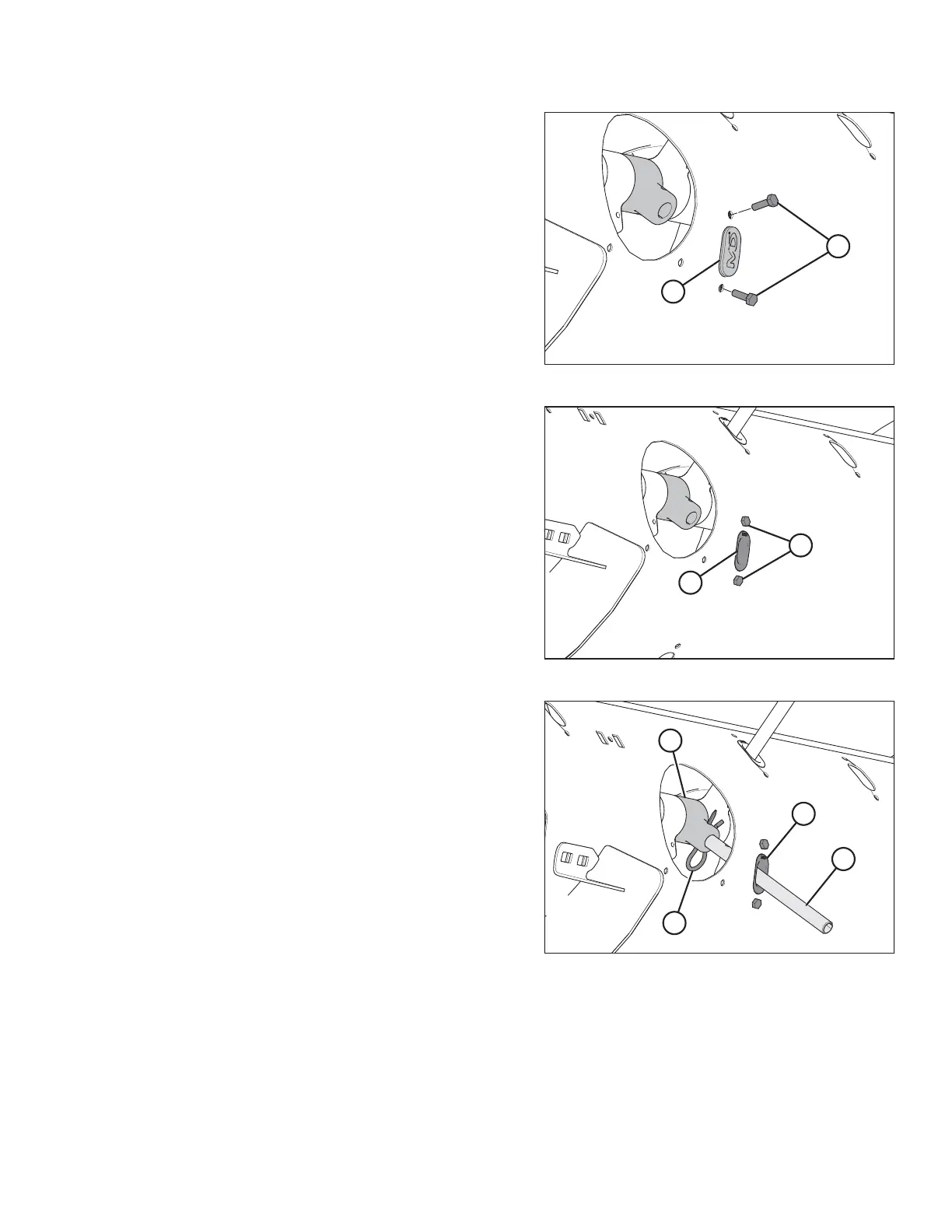
Figure 6.57: Auger Finger Hole
2. Remove two bolts (B), tee nuts, and plug (A).
Figure 6.58: Auger Finger Hole
3. Coat bolts (A) with medium-strength threadlocker
(Loctite
®
243 or equivalent), and then insert plastic finger
guide (B) from inside the auger and secure it with bolts and
tee nuts. Torque bolts to 9 Nm (80 lbf∙ in).
NOTE:
When installing additional fingers, ensure you install an
equal number on each side of the auger.
Figure 6.59: Auger Finger
4. From inside the auger, insert new auger finger (B) through
plastic guide (D).
5. Insert finger (B) into finger holder (C) and secure with
hairpin (A).
NOTE:
Note orientation of hairpin (A). The round part should face
the direction of auger rotation; the formed side (that is, the
S-shaped side) must face the chain drive side of the auger.
FLOAT MODULE SETUP AT DEALER