215184 125 Revision A
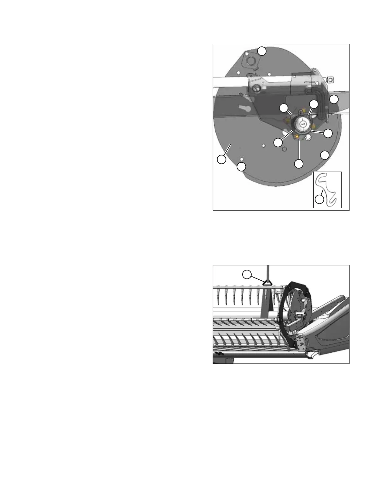
Figure 3.264: Shim Adjustments
A - Shim B - Cam Face C - X1
D - X2 E - X3 F - X4
G - Reel Hub
3. If variation is equal to or greater than the values in Table
3.2, page 124 , add a shim (A) between cam face (B) and
reel hub (G) at the locations specified in the Add Shim at
Location column as follows:
a. Loosen two nuts at the location where shim is to
be added.
b. Insert shim (A) from the hardware bag labelled B and
retighten nuts. Torque to 102 Nm (75 lbf·ft).
NOTE:
If variation is less than the values in Table 3.2, page
124,doNOT add shims.
Installing Reel Lift Cylinders: Left Reel
Figure 3.265: Reel Tube
1. Position sling (A) around the reel tube—close to the
outboard end of reel—and attach sling to a forklift (or
equivalent).
ASSEMBLING THE HEADER AND FLOAT MODULE