215184 308 Revision A
Table 9.1 Combine Voltage Limits (continued)
NOTE:
Some combine models do not support checking sensor output voltage from the cab (early Case 23/2588 series,
CLAAS 500/600/700 Series). For these models, check output voltage manually. Refer to Manually Checking Voltage Range
– One-Sensor System, page 308 or Manually Checking Voltage Range – Two-Sensor System, page 311.
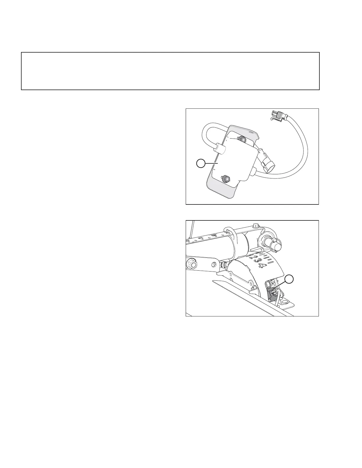
10 Volt Adapter (MD #B6421) – New Holland Combines Only
Figure 9.3: 10 V Adapter (MD #B6421)
New Holland combines with a 10 V system require the 10 V
adapter (A) (MD #B6421) for proper calibration of the auto
header height control (AHHC) feature.
If a 10 V New Holland combine does not have the adapter
installed, the AHHC output will always read 0 V, regardless of
sensor position.
NOTE:
A 10 V adapter is not available for the optional two-sensor
system.
Figure 9.4: Float Indicator Box
Use a voltmeter to measure the voltage between Pin 1 (power)
and Pin 2 (ground) wires at the AHHC sensor (A). This will
determine whether the combine has a 5 V system or a 10 V
system.
NOTE:
The combine key must be in the ON position, but the engine
does not need to be running.
The three possible voltage readings are as follows:
• 0V– combine key is in OFF position, or there is a faulty
harness/bad connection
• 5V– standard combine reading
• 10 V – 10 V combine reading; adapter (MD #B6421) is
required
Manually Checking Voltage Range – One-Sensor System
The one-sensor system is standard for the FM100 Float Module. If equipped with the optional two-sensor system, refer to
Manually Checking Voltage Range – Two-Sensor System, page 311.
The output voltage range of the auto header height control (AHHC) sensors in some combines can be checked from the
cab. For instructions, refer to your combine operator’s manual or the AHHC instructions later in this document.
To manually check the sensor’s output voltage range, follow these steps:
1. Extend guard angle fully; the header angle indicator should be at D.
2. Position the header 150 mm (6 in.) above the ground, and unlock the float.
SETTING UP AUTO HEADER HEIGHT CONTROL