215184 201 Revision A
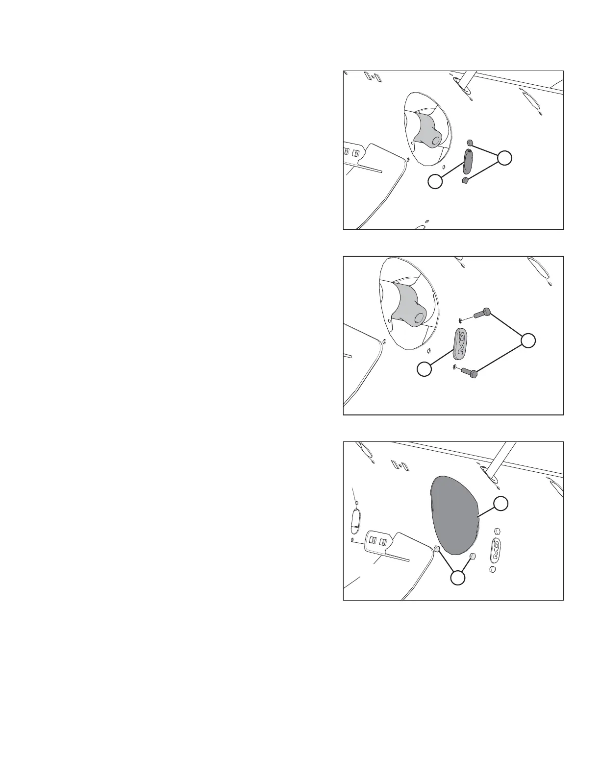
Figure 6.63: Auger Finger Hole
3. Remove bolts (A) and tee nuts securing plastic guide (B) to
the auger, and remove the guide from inside the auger.
Figure 6.64: Plug
4. Coat bolts (B) with medium-strength threadlocker
(Loctite
®
243 or equivalent), and then position plug (A) into
the hole from inside the auger. Secure with two M6 hex
head bolts (B) and tee nuts. Torque to 9 Nm (80 lbf∙ in).
Figure 6.65: Auger Access Hole Cover
5. Coat bolts (A) with medium-strength threadlocker
(Loctite
®
243 or equivalent) and reinstall access cover (B).
Secure the access cover in place with bolts (A). Torque bolts
to 9 Nm (80 lbf∙in).
FLOAT MODULE SETUP AT DEALER