215184 310 Revision A
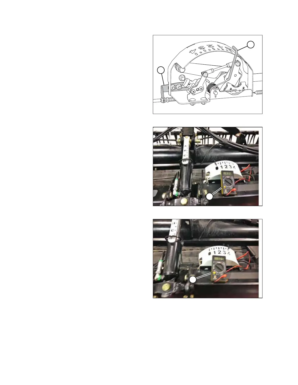
Figure 9.7: Float Indicator Box
5. Adjust cable take-up bracket (B) (if necessary) until float
indicator pointer (A) is on 0.
Figure 9.8: Measuring Voltage at Float Indicator Box
6. Use a voltmeter (A) to measure the voltage between the
ground (Pin 2) and signal (Pin 3) wires at the AHHC sensor
in the float indicator box. Ensure it is at the high voltage
limit for the combine. For voltage limit chart, refer to
Table 9.1, page 307.
NOTE:
The wiring harness connector must be attached to the
sensor. Do NOT disconnect it.
Figure 9.9: Measuring Voltage at Float Indicator Box
7. Fully lower the combine feeder house, and float the header
up off the down stops (float indicator should be at 4, and
the float module should be fully separated from the
header).
NOTE:
You may need to hold the HEADER DOWN switch for a few
seconds to ensure the feeder house is fully lowered.
8. Use a voltmeter (A) to measure the voltage between the
ground and signal wires at the AHHC sensor in the float
indicator box. It should be at the low voltage limit for the
combine. For voltage limit chart, refer to Table 9.1, page
307.
NOTE:
The wiring harness connector must be attached to the
sensor. Do NOT disconnect it.
9. If the sensor voltage is not within the low and high limits, or if the range between the low and high limits is
insufficient, adjust the voltage limits. Refer to Adjusting Voltage Limits – One-Sensor System, page 314.
SETTING UP AUTO HEADER HEIGHT CONTROL