215184 359 Revision A
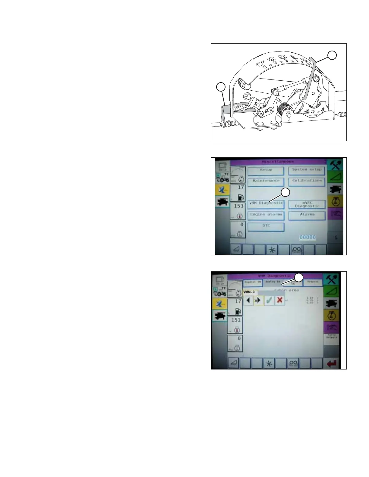
Figure 9.120: Float Indicator Box
3. Adjust cable take-up bracket (B) (if necessary) until float
indicator pointer (A) is on 0.
Figure 9.121: Challenger Combine Display
4. Go to the FIELD page on the combine monitor, and then
press the diagnostics icon. The MISCELLANEOUS page
displays.
5. Press VMM DIAGNOSTIC button (A). The VMM DIAGNOSTIC
page displays.
Figure 9.122: Challenger Combine Display
6. Go to ANALOG IN tab (A), and then select VMM MODULE 3
by pressing the text box below the four tabs. The voltage
from the AHHC sensor is now displayed on page as HEADER
HEIGHT RIGHT POT and HEADER HEIGHT LEFT POT. The
readings may be slightly different.
SETTING UP AUTO HEADER HEIGHT CONTROL