DMTA-10004-01EN, Rev. D, November 2016
Chapter 10
150
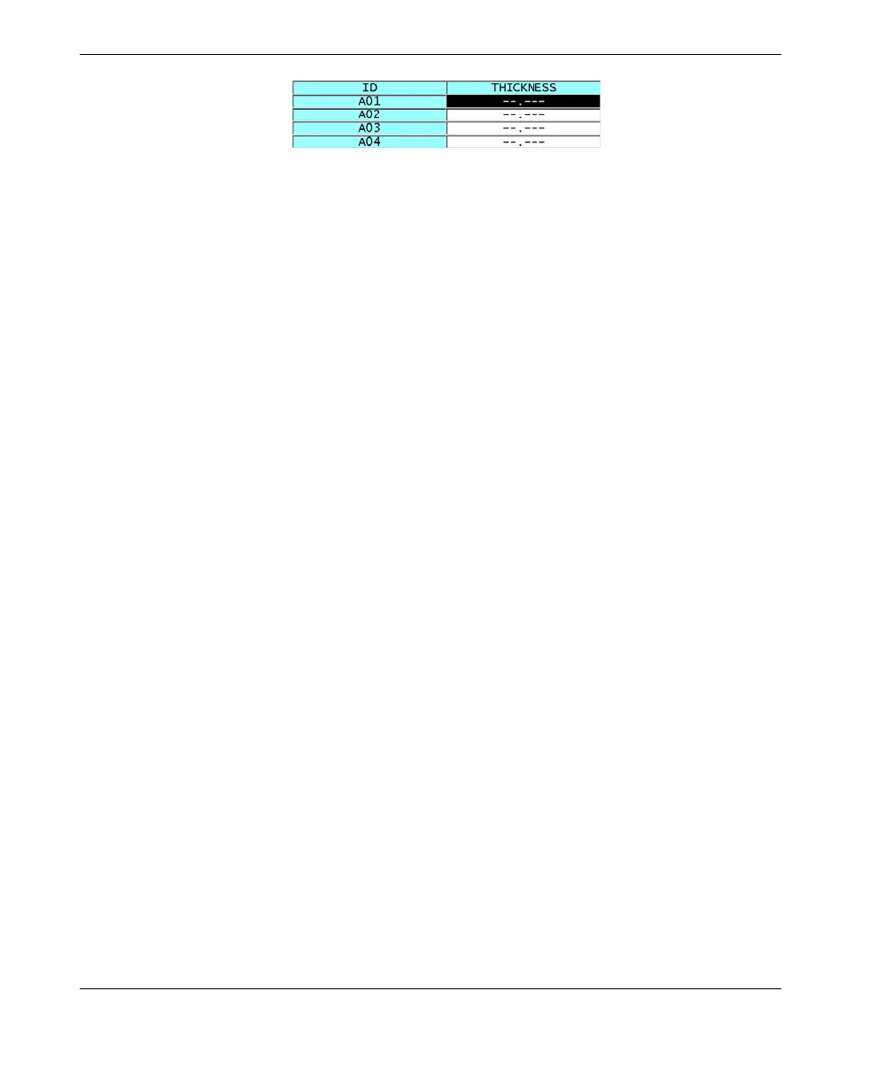
Figure 10‑12 Example of a linearized DB grid
8. Set DATA CELL FLAG to one of the available options to display a single data flag
with each data cell in the DB grid. The data cell flag is a letter that appears in a
small box to the right of the thickness value in the data cell (see Figure 10-8 on
page 147). The available options are:
NONE
No data cell flag appears.
MIN/MAX
“m” indicates a minimum thickness.
“M” indicates a maximum thickness.
ALARM
“L” indicates any kind of low alarm condition including a standard low alarm
condition or a previous thickness alarm.
“H” indicates any high alarm condition.
A‑SCAN
“W” indicates that a waveform is stored with the thickness.
9. Set GRID COLOR OPTION to ON to activate usage of low, mid, and high range
colors for the grid cell background.
10. Set LO RANGE COLOR to the desired cell background color (RED, YELLOW, or
GREEN) when the cell thickness value is smaller than the LO RANGE VALUE.
11. Set MID RANGE COLOR to the desired cell background color (RED, YELLOW,
or GREEN) when the cell thickness value is between the LO RANGE VALUE and
the HI RANGE VALUE.
12. Set HI RANGE VALUE to the desired cell background color (RED, YELLOW, or
GREEN) when the cell thickness value is higher than the HI RANGE VALUE.
10.4.2 Changing the Highlighted Cell in the DB Grid
You can easily move the selected cell in the DB grid using the arrow keys.