DMTA-10004-01EN, Rev. D, November 2016
Chapter 12
218
The thickness readings at this point may not be accurate because a proper zero offset
for the transducer has not yet been set.
c) Couple the transducer to the thinnest test block step.
d) If necessary, press [GAIN] to adjust the gain so that the instrument properly
detects the back-wall echo.
e) If necessary, adjust the extend blank so that the gage is making proper
detection on the back-wall signal (see “Blanking Adjustments in Manual
Echo-to-Echo Detection Mode” on page 83).
f) Ensure that the instrument properly detects echoes on all test block steps.
4. Activate the V-path function (see “Activating the V-Path Function” on page 216
for details).
5. Couple the transducer to a thick sample representing the thickest material that
you will measure.
6. Press [CAL VEL].
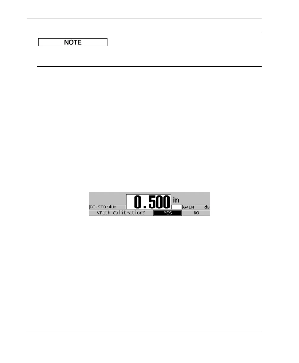
7. In the help text bar, select YES to the VPath Calibration? prompt (see Figure 12-4
on page 218).
Figure 12‑4 Answering YES at the V‑path calibration prompt
8. While the transducer is coupled to the thick sample and getting a steady thickness
reading, press [ENTER].
9. In the V‑PATH CALIBRATION screen, edit the point 1 value to match the known
thickness (see Figure 12-5 on page 219).