DMTA-10004-01EN, Rev. D, November 2016
Labels and Symbols
1
Labels and Symbols
Safety-related labels and symbols are attached to the instrument at the locations
shown in Figure i-1 on page 1 and Figure i-2 on page 2. If any or all of the labels or
symbols are missing or illegible, please contact Olympus.
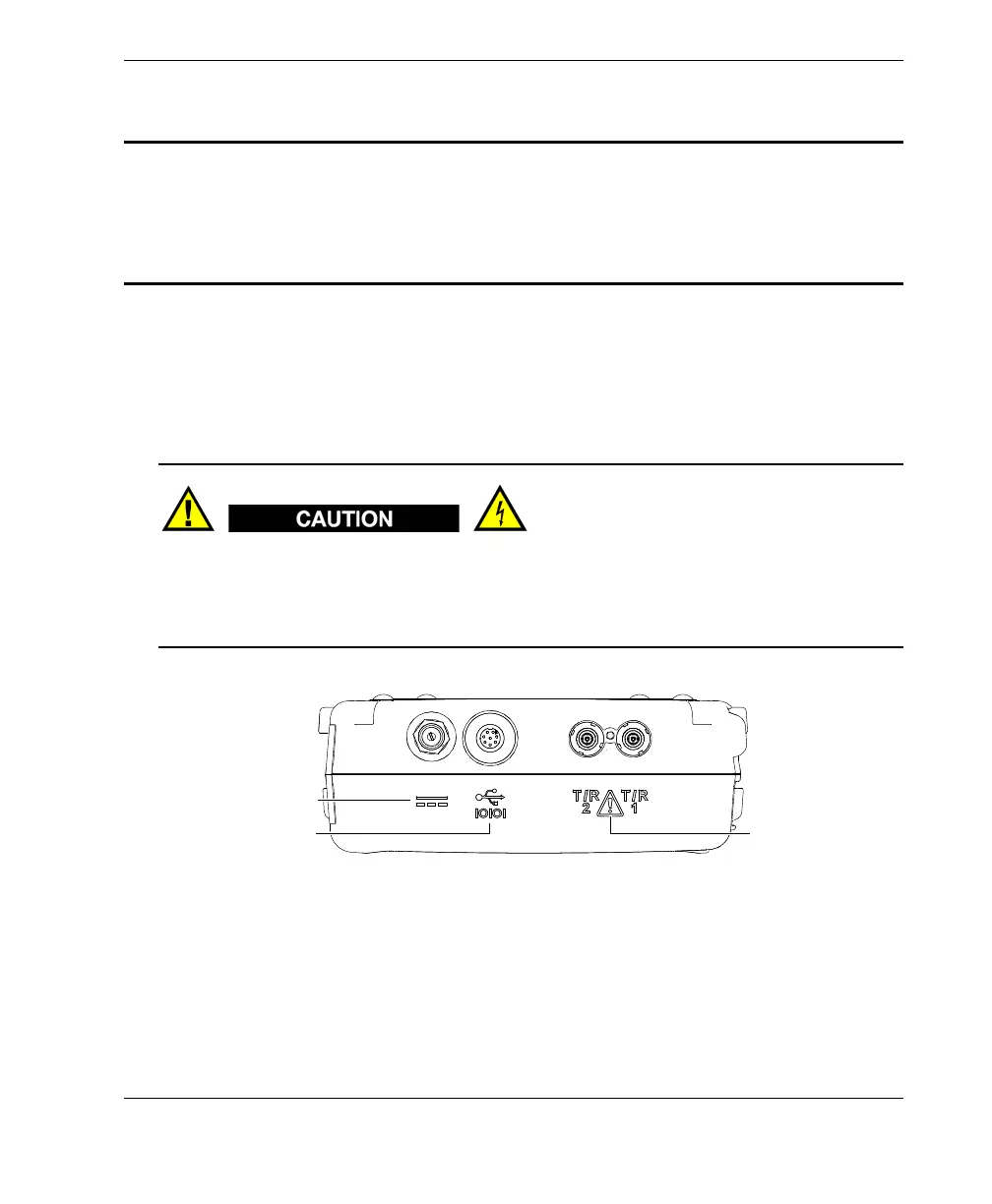
Do not touch the inner conductor of the T/R 1 and T/R 2 connectors to avoid risks of
an electric shock. Up to 200 V can be present on the inner conductor. The warning
symbol between the Transmit/Receive (T/R) connector markings is shown in
Figure i-1 on page 1.
Figure i‑1 The warning symbol between the T/R connectors
Top end view
Warning symbol
Direct current symbol
USB and RS-232
symbols