Startup Procedure and Test Run
4
4.9 Auto-Tuning
SIEPCYEUOQ2V01A Q2V Technical Manual 125
Input Data Parameter Unit
Auto-Tuning Mode
(T1-01 Setting)
Rotational Auto-Tuning
(0)
Stationary Auto-Tuning
1
(1)
Stationary Line-Line
Resistance
(2)
Test Mode Selection
*3
T1-12 - - x
*4
-
No-load Voltage
T1-13 V x x -
*1 Shows 0 Hz as the default value. If you do not know the Motor Rated Slip Frequency, keep the setting at 0 Hz.
*2 Input this value when A1-02 = 0 [Control Method = V/f Control].
*3 If T1-12 = 1 [Test Mode Selection = Yes], when you run the motor in Drive Mode for the first time after Auto-Tuning, the drive will
automatically set E2-02 [Mot Rated Slip] and E2-03 [Mot No-Load Current].
*4 Input this value when T1-10 [Motor Rated Slip Frequency] = 0 Hz.
◆ Auto-Tuning for PM Motors
This section gives information about Auto-Tuning for PM motors. Auto-Tuning sets motor parameters E1-xx and
E5-xx.
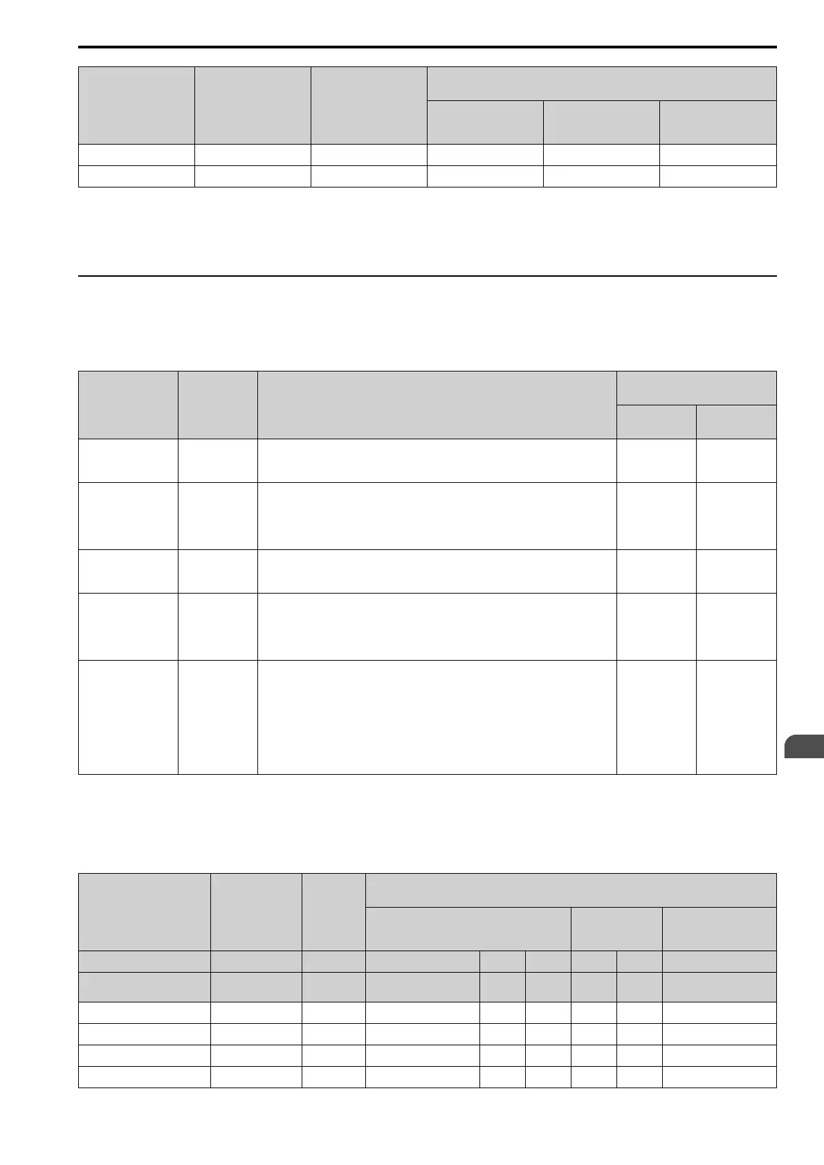
Table 4.9 Auto-Tuning for PM Motors
Mode
Parameter
Settings
Application Conditions and Benefits
Applicable Control Method
(A1-02 Setting)
PM OLVector
(5)
PM AOLVector
(6)
Manual Entry w/ Motor
Data Sheet
T2-01 = 0
• When the information from the motor test report or motor nameplate is available.
• Rotational/Stationary Auto-Tuning that energizes the motor is not done. Manually
input the necessary motor parameters.
x x
PM Stationary Auto-
Tuning
T2-01 = 1
• When the information from the motor test report or motor nameplate is not available.
Note:
With Stationary Auto-Tuning, the energized drive stays stopped for approximately 1
minute. During this time, the drive automatically measures the necessary motor
parameters.
x x
PM Stationary Auto-
Tuning for Stator
Resistance
T2-01 = 2
• After Auto-Tuning, the wiring distance between the drive and motor changed by 50 m
(164 ft) or more.
• When the motor output and drive capacity are different.
x x
PM Motor Code
Selection
T2-01 = 4
• When the information from the motor test report or motor nameplate is not available.
• When you can decouple the motor and load and the motor can rotate freely while Auto-
Tuning.
• The drive will automatically set the values measured during Auto-Tuning to the motor
parameters.
x x
High Frequency
Injection
T2-01 = 5
• Automatically sets the control parameters that are necessary to set n8-35 = 2
[InitRotorPos Selection = ] or n8-57 = 1 [High-Freq Injection = Enabled].
• Applicable to IPM motors only.
• Do Auto-Tuning with the motor connected to the drive.
Note:
When you set n8-35 = 1 or n8-57 = 1, do High Frequency Injection Auto-Tuning. Set
the data on the motor nameplate to the drive before you do High Frequency Injection
Auto-Tuning. In High Frequency Injection Auto-Tuning, the drive energizes the
stopped motor and automatically adjusts the parameters.
x x
■ Input Data for PM Motor Auto-Tuning
To do Auto-Tuning, input data for these items that have an "x". Before starting Auto-Tuning, prepare the motor
test report or record the information on the motor nameplate as a reference.
Table 4.10 Input Data for PM Motor Auto-Tuning
Input Data Parameter Unit
Auto-Tuning Mode
(T2-01 Setting)
PM Motor Parameter Settings
(0)
PM Static Full
AutoTune
(1)
PM Static R Autotune
(2)
Control Method Selection A1-02 - 5, 6 5 6 5 6 5, 6
PM Motor Code Selection T2-02 -
Motor code of Yaskawa
motor
*1
FFFF
*2
FFFF
*2
- - -
PM Motor Type T2-03 - - - - x x -
PM Motor Rated Power T2-04 kW - x x x x -
PM Motor Rated Voltage T2-05 V - x x x x -
PM Motor Rated Current T2-06 A - x x x x x

 Loading...


