Parameter List
11
11.16 U: MONITORS
SIEPCYEUOQ2V01A Q2V Technical Manual 399
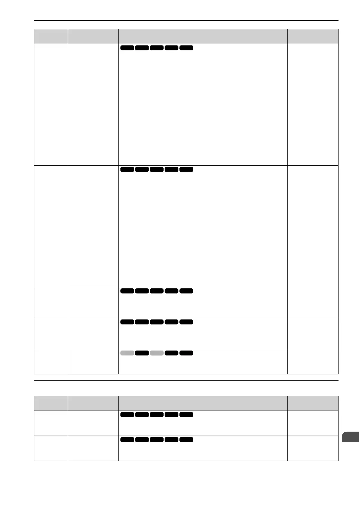
No.
(Hex.)
Name Description MFAO Signal Level
U4-22
(07DE)
Mbus CmdWord Value
Shows the operation signal (register 0001H) sent to the drive from Modbus communications as a
4-digit hexadecimal number (zero suppress).
The keypad shows the operation signal as specified by these rules:
bit 0 : Forward run/Stop
bit 1 : Reverse run/Stop
bit 2 : External fault
bit 3 : Fault Reset Procedure
bit 4 : Multi-function input 1
bit 5 : Multi-function input 2
bit 6 : Multi-function input 3
bit 7 : Multi-function input 4
bit 8 : Multi-function input 5
bit 9 : Multi-function input 6
bit A : Multi-function input 7
bit B : Not used (normal value of 0).
bit C : Not used (normal value of 0).
bit D : Not used (normal value of 0).
bit E : Not used (normal value of 0).
bit F : Not used (normal value of 0).
No signal output available
U4-23
(07DF)
Option CmdWord Value
Shows the operation signal (register 0001H) sent to the drive from Modbus communications as a
4-digit hexadecimal number.
The keypad shows the operation signal as specified by these rules:
bit 0 : Forward run/Stop
bit 1 : Reverse run/Stop
bit 2 : External fault
bit 3 : Fault Reset Procedure
bit 4 : Multi-function input 1
bit 5 : Multi-function input 2
bit 6 : Multi-function input 3
bit 7 : Multi-function input 4
bit 8 : Multi-function input 5
bit 9 : Multi-function input 6
bit A : Multi-function input 7
bit B : Not used (normal value of 0).
bit C : Not used (normal value of 0).
bit D : Not used (normal value of 0).
bit E : Not used (normal value of 0).
bit F : Not used (normal value of 0).
No signal output available
U4-24
(07E6)
No of Travels(L)
Shows the lower 4 digits of the drive run count.
Note:
The drive run count appears as an 8-digit number. Monitor U4-25 [No of Travels(H)] shows
the upper 4 digits and U4-24 shows the lower 4 digits.
No signal output available
U4-25
(07E7)
No of Travels(H)
Shows the lower 4 digits of the drive run count.
Note:
The drive run count appears as an 8-digit number. Monitor U4-25 shows the upper 4 digits
and U4-24 [No of Travels(L)] shows the lower 4 digits.
No signal output available
U4-52
(1592)
Torque Ref from Comm
Displays the torque reference given to the drive via a serial communication option card or via
Modbus communications as a decimal number.
Unit: 0.1%
10 V = 100% (-10 V to +10
V)
◆ U5: PID
No.
(Hex.)
Name Description MFAO Signal Level
U5-01
(0057)
PID Feedback
Shows the PID control feedback value. Parameter b5-20 [PID Unit Selection] sets the display
units.
Unit: 0.01%
10 V = Maximum
frequency (-10 V to +10 V)
U5-02
(0063)
PID Input
Shows the change between the PID setpoint and PID feedback (the quantity of PID input) as a
percentage of the maximum output frequency.
Unit: 0.01%
10 V = Maximum
frequency (-10 V to +10 V)

 Loading...


