Parameter Details
12
12.7 H: TERMINALS
SIEPCYEUOQ2V01A Q2V Technical Manual 613
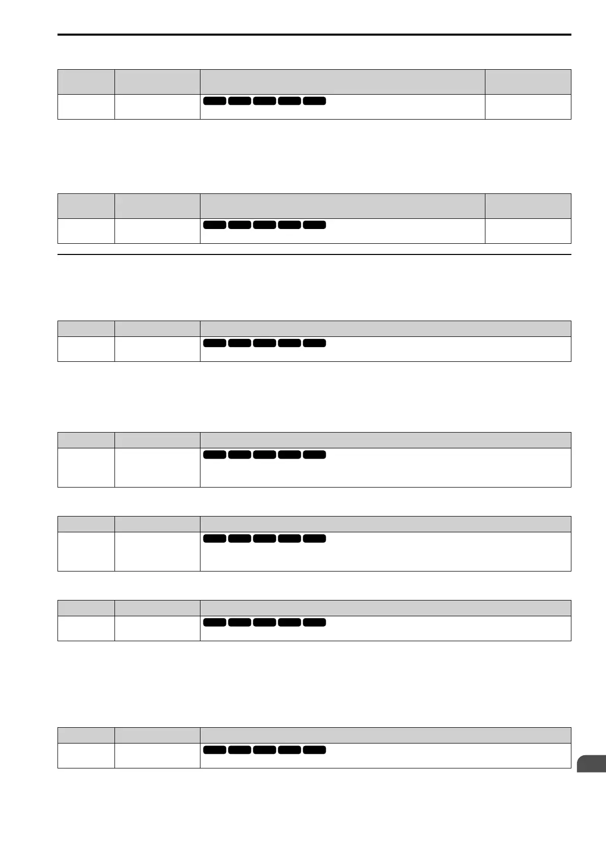
■ H3-42: 15C3h Input Function
No.
(Hex.)
Name Description
Default
(Range)
H3-42
(0B62)
15C3h Input Function
Sets the Modbus AI3 function.
0
(0, 3, 6 - 2F)
You can use the MFAI function from Modbus communications. Use this parameter to set the function. Sets the
input for the function in Modbus register 15C3.
Refer to H3: ANALOG INPUTS on page 608 for the setting values.
■ H3-43: Mbus In FilterTime Const
No.
(Hex.)
Name Description
Default
(Range)
H3-43
(117F)
Mbus In FilterTime Const
Sets the time constant to apply a primary delay filter to the Modbus analog input terminal.
0.00 s
(0.00 - 2.00 s)
◆ MFAI Setting Values
This section gives information about the functions set with H3-02 and H3-10.
■ 0: Through Mode
Setting Value Function Description
0 Through Mode
Use this setting for unused terminals or to use terminals in through mode.
When you set a terminal that is not in use to 0, you can use the signal input to the terminal as PLC analog signal
input through Modbus communications or the communication option. This input signal does not have an effect on
drive operation. This functions the same as setting 100 (Through Mode).
■ 1: AuxFreqRef1
Setting Value Function Description
1 AuxFreqRef1
Sets Reference 2 through multi-step speed reference to enable the command reference (Auxiliary Frequency Reference 1) from
the analog input terminal set here. This value is a percentage where the Maximum Output Frequency setting is a setting value of
100%.
■ 2: AuxFreqRef2
Setting Value Function Description
2 AuxFreqRef2
Sets Reference 3 through multi-step speed reference to enable the command reference (Auxiliary Frequency Reference 2) from
the analog input terminal set here. This value is a percentage where the Maximum Output Frequency setting is a setting value of
100%.
■ 3: FrqBIAS Frq
Setting Value Function Description
3 FrqBIAS Frq
Enters the bias value added to the frequency reference as a percentage of the maximum output frequency.
The drive adds the input value from the MFAI terminal set with this function to the frequency reference as the bias
value.
Note:
When you select d1-01 to d1-16 or d1-17 [Reference 1 to 16 or Jog Reference] as the frequency reference, it will disable this function.
■ 4: Freq Ref/BIAS
Setting Value Function Description
4 Freq Ref/BIAS
The input value from the MFAI terminal set with this function becomes the master frequency reference.
• You can copy the configuration to more than one of the analog input terminals AI1 and AI2. When you set more
than one analog input terminal with the master frequency reference, the sum value becomes the frequency bias.
 Loading...


