6.3 Modbus Communications
200 SIEPCYEUOQ2V01A Q2V Technical Manual
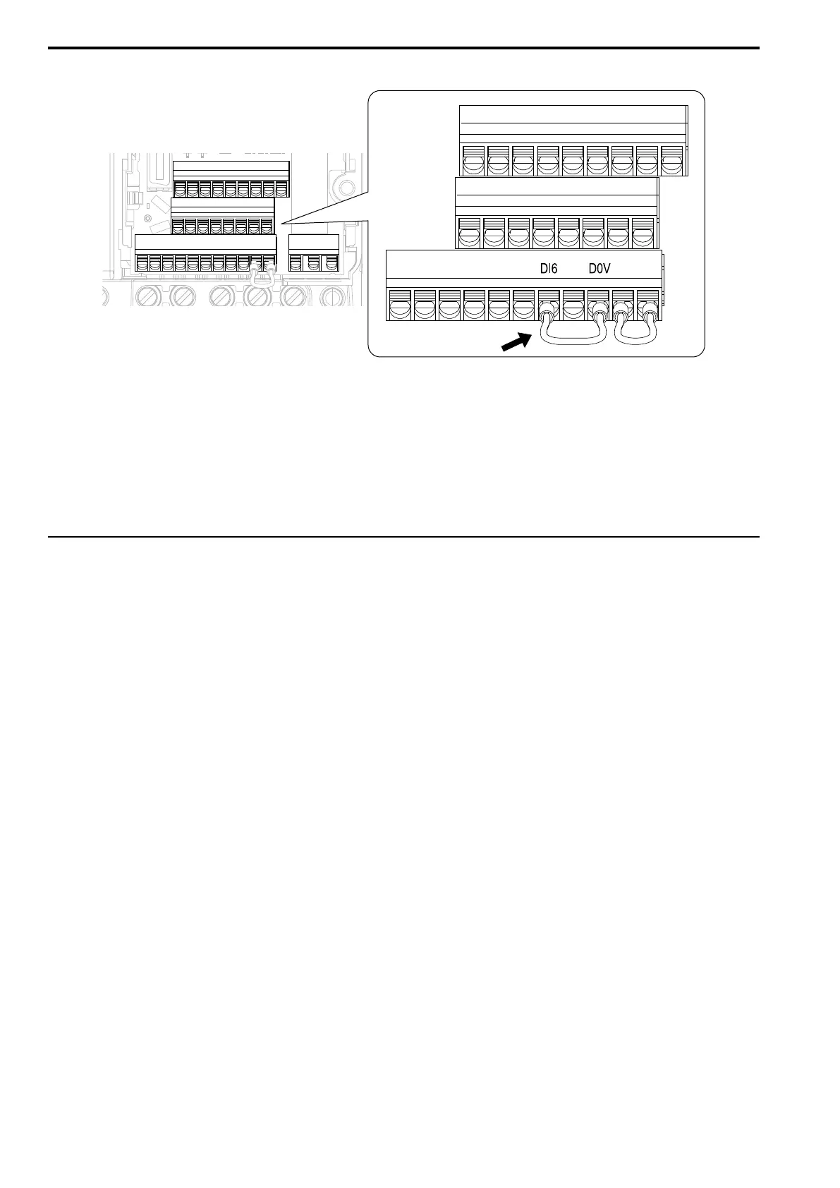
4. Connect a jumper between control circuit terminals DI6 and D0V.
Figure 6.12 Self-Diagnostics Jumper Terminals
5. Energize the drive.
6. When normal, the keypad will show PASS [Modbus Communications Test Mode Normal].
When there is an error, the keypad will show CE [Modbus Communications Error].
7. De-energize the drive.
8. Disconnect the wire jumper between terminals DI6 and D0V. Set terminal DI6 to its initial function.
Self-Diagnostics is complete and the drive returns to its usual function.
◆ Communications Data Table
The communication data types are command data, monitor data, and broadcast message.
■ Command Data
You can read and write command data.
Note:
Set the reserved bit to 0. Do not write the data in the reserved register or the monitor register.

 Loading...


