Parameter Details
12
12.7 H: TERMINALS
SIEPCYEUOQ2V01A Q2V Technical Manual 627
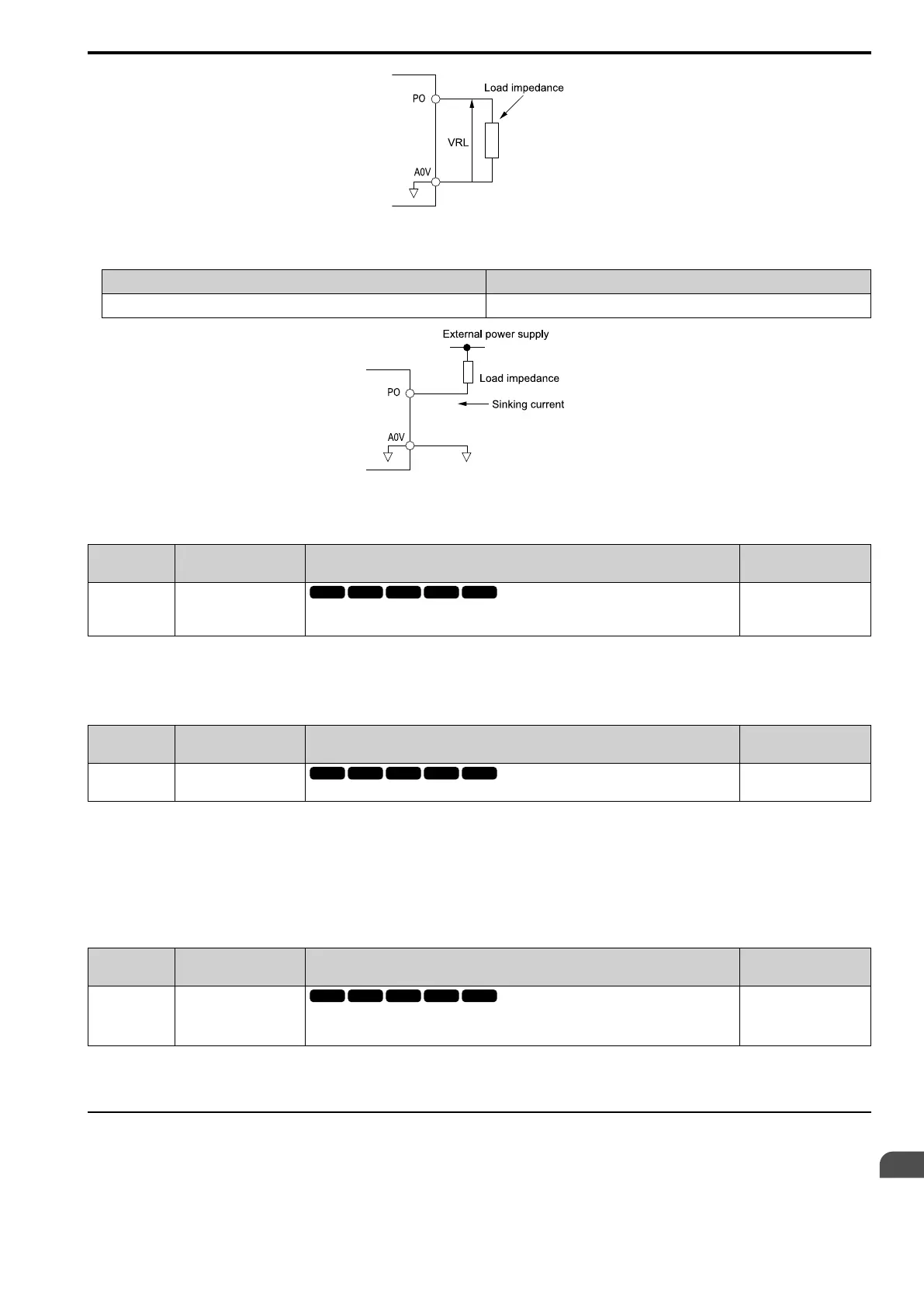
Figure 12.102 Circuit Diagram When Used as the Sourcing Output
• Use the pulse train monitor as the sinking input
External Power Supply (V) 12 VDC ± 10%, 15 VDC ± 10%
Sinking current (mA) 16 mA or less
Figure 12.103 Circuit Diagram When Used as the Sinking Input
■ H6-07: PO Freq.Scaling
No.
(Hex.)
Name Description
Default
(Range)
H6-07
(0432)
RUN
PO Freq.Scaling
Sets the frequency of the pulse train output signal used when the monitor set with H6-06 [PO
Mon.Selection] is 100%.
1440 Hz
(0 - 32000 Hz)
When H6-06 = 102 [PO Mon.Selection = Output Frequency] and H6-07 = 0, the pulse train output terminal PO
outputs the same frequency as the drive output frequency.
■ H6-08: PI Minimum Frequency
No.
(Hex.)
Name Description
Default
(Range)
H6-08
(043F)
PI Minimum Frequency
Sets the minimum frequency of the pulse train signal that terminal PI can detect.
0.5 Hz
(0.1 - 1000.0 Hz)
• When you input a pulse train frequency that is less than the value of H6-08, the pulse train input is 0.0 Hz.
• Set H6-01 [PI Pulse Train Function] = 0 [Freq Ref], 1 [PIDFbk Value], or 2 [PID SP Value] to enable this
parameter.
• When H6-01 = 3 [PG Feedback], the drive applies the setting of F1-14 [Enc PGOpen Time for Detection] to
the minimum frequency.
■ H6-09 PO Volt.PhaseSync Selection
No.
(Hex.)
Name Description
Default
(Range)
H6-09
(156E)
PO Volt.PhaseSync
Selection
Set whether to output the pulse synchronized with drive output voltage phase from the pulse train
monitor output terminal PO. This parameter is only enabled when H6-06 = 102 [PO Mon.
Selection = Output Frequency] and H6-07 = 0 [PO Freq.Scaling = 0 Hz].
0
(0, 1)
0 : Disabled
1 : Enabled
◆ H7: VIRTUAL INPUT OUTPUT
The virtual I/O function performs the following.
• Inputs the result of the output from the MFDO terminal to the MFDI terminal without external wiring.
• Inputs the result of the output from the MFAO terminal to the MFAI terminal without external wiring.

 Loading...


