3.5 Control Circuit Wiring
78 SIEPCYEUOQ2V01A Q2V Technical Manual
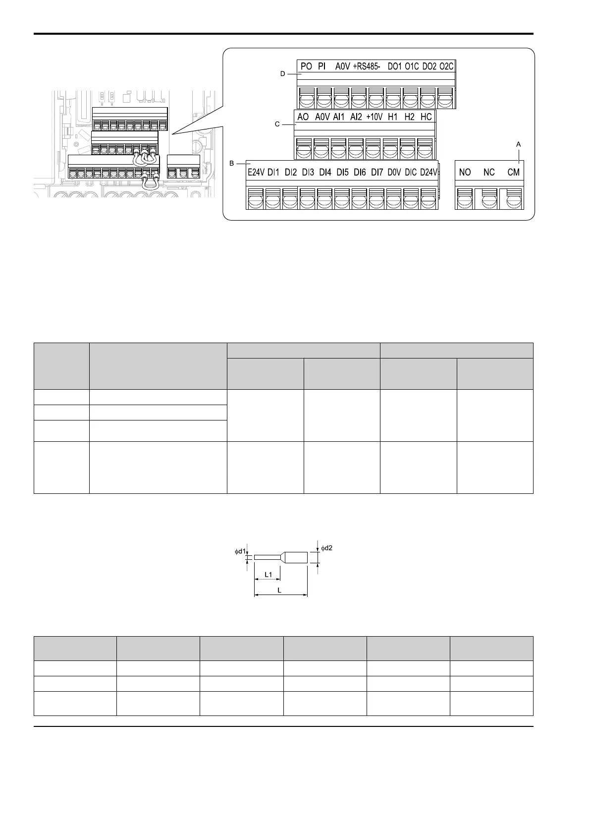
A - Terminal block (TB2)
B - Terminal block (TB1-1)
C - Terminal block (TB1-2)
D - Terminal block (TB1-3)
Figure 3.21 Control Circuit Terminal Arrangement
■ Control Circuit Wire Gauges and Tightening Torques
Use the tables in this chapter to select the correct wires. Use shielded wire to wire the control circuit terminal
block. Use crimp ferrules on the wire ends to make the wiring procedure easier and more reliable.
Table 3.14 Control Circuit Wire Gauges and Tightening Torques
Terminal Block Terminal
Bare Wire Crimp Ferrule
Recommended
Gauge
mm
2
(AWG)
Applicable Gauge
mm
2
(AWG)
Recommended
Gauge
mm
2
(AWG)
Applicable Gauge
mm
2
(AWG)
TB1-1 E24V, DI1 - DI7, D0V, DIC, D24V
0.75
(18)
• Stranded wire
0.25 - 1.0
(24 - 17)
• Solid wire
0.25 - 1.5
(24 - 16)
0.5
(20)
0.25 - 0.5
(24 - 20)
TB1-2 AO, A0V, AI1, AI2, +10V, H1, H2, HC
TB1-3
PO, PI, A0V, RS485+, RS485-, DO1, O1C,
DO2, O2C
TB2 NO, NC, CM
0.75
(18)
• Stranded wire
0.25 - 1.5
(24 -16)
• Solid wire
0.25 - 1.5
(24 - 16)
0.5
(20)
0.25 - 1.0
(24 - 17)
Crimp Ferrules
Attach an insulated sleeve when you use crimp ferrules.
Use the CRIMPFOX 6, a crimping tool made by PHOENIX CONTACT.
Figure 3.22 External Dimensions of Crimp Ferrules
Table 3.15 Crimp Ferrule Models and Sizes
Wire Gauge
mm
2
(AWG)
Model L (mm) L1 (mm) φd1 (mm) φd2 (mm)
0.25 (24) AI 0.25-8YE 12.5 8 0.8 2.0
0.34 (22) AI 0.34-8TQ 12.5 8 0.8 2.0
0.5 (20)
AI 0.5-8WH,
AI 0.5-8OG
14 8 1.1 2.5
◆ Wiring the Control Circuit Terminal
Wire the grounding terminal and main circuit terminals, then wire the control circuit terminals.

 Loading...


