12.2 b: APPLICATION
444 SIEPCYEUOQ2V01A Q2V Technical Manual
12.2 b: APPLICATION
b parameters set these functions:
• Frequency reference source/Run command source
• Stopping method settings
• DC Injection Braking
• Speed Search
• Timer Function
• PID control
• Dwell function
• Energy-Saving Control
◆ b1: OPERATION MODE SELECT
b1 parameters set the operation mode for the drive.
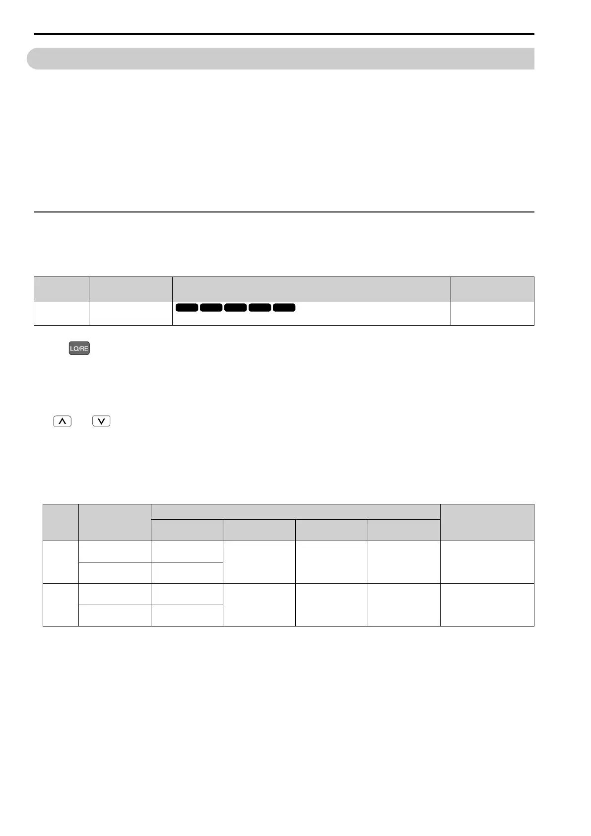
■ b1-01: Freq. Ref. Sel. 1
No.
(Hex.)
Name Description
Default
(Setting Range)
b1-01
(0180)
Freq. Ref. Sel. 1
Sets the input method for the frequency reference.
1
(0 - 4)
Note:
• Push on the keypad to set the input mode to LOCAL and use the keypad to enter the frequency reference.
• If the frequency reference is 0 Hz or less than the value set in E1-09 [Min Output Frequency] and the drive receives the Run command,
the RUN LED on the keypad will flash. Examine the setting for the frequency reference input and enter a value ≥ E1-09.
0 : Keypad
Use the keypad to enter the frequency reference.
Use and on the keypad to change the frequency reference.
1 : Analog Input
Use MFAI terminals AI1 and AI2 to input an analog frequency reference with a voltage or current input signal.
• Voltage Input
Refer to Table 12.6 to use a voltage signal input to one of the MFAI terminals.
Table 12.6 Frequency Reference Voltage Input
Terminal
Terminal Signal
Level
Parameter Settings
Note
Signal Level
Selection
Function Selection Gain Bias
AI1 0 - 10 V (Lower Limit
at 0)
H3-01 = 0 H3-02 = 4
[Freq Ref/BIAS]
H3-03 H3-04
-
0 - 10 V (Bipolar
Reference)
H3-01 = 1
AI2 0 - 10 V (Lower Limit
at 0)
H3-01 = 0 H3-10 = 4
[Freq Ref/BIAS]
H3-11 H3-12 Set DIP switch S1 to “V” for
voltage input.
0 - 10 V (Bipolar
Reference)
H3-01 = 1

 Loading...


