Electrical Installation
3
3.5 Control Circuit Wiring
SIEPCYEUOQ2V01A Q2V Technical Manual 77
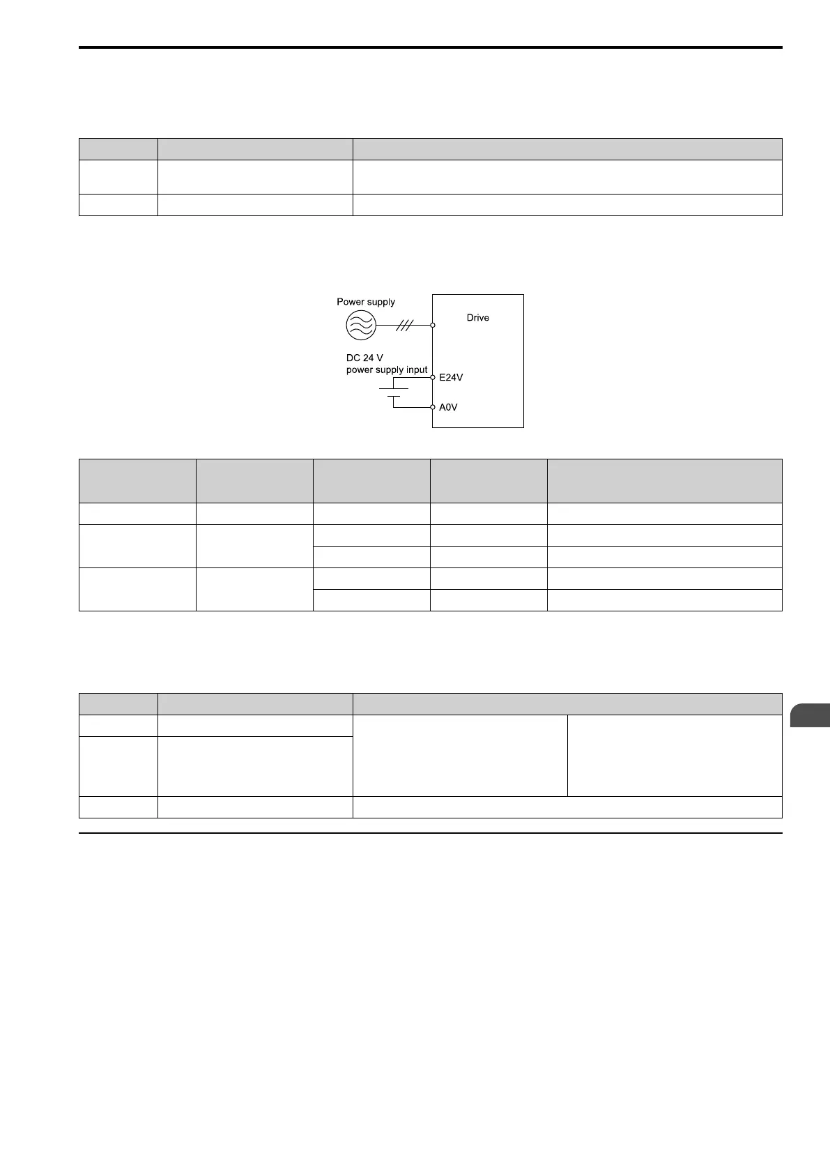
■ External Power Supply Input Terminals
This chapter contains a list of the functions of the external power supply input terminals.
Table 3.11 External Power Supply Input Terminals
Terminal Name (Default) Function
E24V External 24 V power supply input
Supplies backup power to the drive control circuit, keypad, and option board.
21.6 VDC to 26.4 VDC, 700 mA
A0V External 24 V power supply ground 0 V
Alarm Display When You Use External 24 V Power Supply
When you use an external 24 V power supply, an alarm is detected as shown below if you set o2-23 [Ext24V Off
Warning Display] and o2-26 [Ext24V Mode Warning Display] for the main circuit power supply. Set the alarm
display as needed.
Table 3.12 Power Supply Used and the Alarm Display
Main circuit power
supply
External 24 V power
supply
o2-23
[Ext24V Off Warning
Display]
o2-26
[Ext24V Mode Warning
Display]
Alarm display
ON ON - -
-
ON OFF 0 [Disabled] -
-
1 [Enabled] - L24v [Loss of External Power 24 Supply]
OFF ON - 0 [Disabled] "Ready" LED light flashes quickly
- 1 [Enabled] EP24v [External Power 24V Supply]
■ Serial Communication Terminals
This chapter contains a list of serial communication terminals and functions.
Table 3.13 Modbus Communication
Terminal Terminal Name Function (Signal Level)
RS485+ Communication input/output (+)
Modbus communications
Use an RS-485 cable to connect the drive.
Note:
Set DIP switch S2 to ON to enable the
termination resistor in the last drive in a Modbus
network.
• RS-485
• Modbus communication protocol
• Maximum 115.2 kbps
RS485- Communication output (-)
A0V Signal ground
0 V
◆ Control Circuit Terminal Configuration
The control circuit terminals are in the positions shown in this chapter.

 Loading...


