Electrical Installation
3
3.6 Control I/O Connections
SIEPCYEUOQ2V01A Q2V Technical Manual 81
3.6 Control I/O Connections
This section gives information about the settings for the listed control circuit I/O signals.
• MFDI (terminals DI1 to DI7)
• Pulse train output (terminal PO)
• MFAI (terminal AI2)
• MFAO (terminal AO)
• Modbus communications (terminals RS485+, RS485-, A0V)
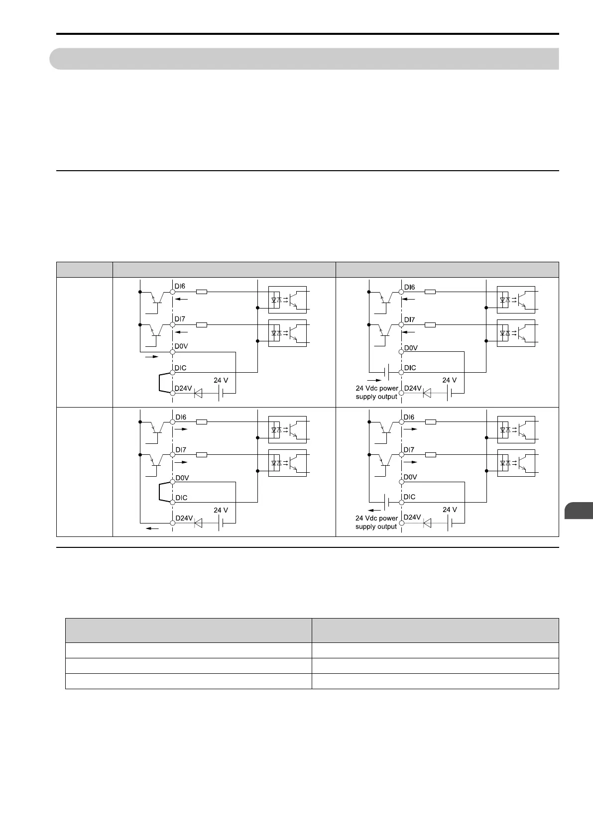
◆ Set Sinking Mode/Sourcing Mode
Close the circuit between terminals DIC-D24V and DIC-D0V to set the sinking mode/sourcing mode and the
internal/external power supply for the MFDI terminals. The default setting for the drive is internal power supply
sinking mode.
NOTICE: Do not close the circuit between terminals D24V and D0V. A closed circuit between these terminals will cause
damage to the drive.
Mode Internal Power Supply (Terminal D0V-D24V) External 24 V power supply
Sinking Mode
(NPN)
Sourcing Mode
(PNP)
◆ Pulse Train Output
You can use pulse train monitor output terminal PO for sourcing mode or for sinking mode.
• Use for sourcing mode
The load impedance changes the voltage level of the pulse train output signal.
Load Impedance
R
L
(kΩ)
Output Voltage
V
PO
(V)
1.5 kΩ or more 5 Vor more
4.0 kΩ or more 8 Vor more
10 kΩ or more 10 Vor more
Note:
Use the formula below to calculate the necessary load resistance (kΩ) to increase output voltage V
PO
(V).

 Loading...


