Electrical Installation
3
3.3 Main Circuit Wiring
SIEPCYEUOQ2V01A Q2V Technical Manual 45
3.3 Main Circuit Wiring
This section gives information about the functions, specifications, and procedures necessary to safely and
correctly wire the main circuit in the drive.
NOTICE: The drive can fail if users frequently turn the drive ON and OFF with the MC on the power source side to Run and
Stop the drive. Incorrect operation can decrease the service life of the relay contacts and electrolytic capacitors. If you
frequently use the magnetic contactor on the power source side to Run and Stop the drive, it can cause drive failure.
Note:
Soldered wire connections can become loose over time and cause unsatisfactory drive performance.
◆ Motor and Main Circuit Connections
WARNING! Electrical Shock Hazard. Do not connect terminals R/L1, S/L2, T/L3, L/L1, N/L2, U/T1, V/T2, W/T3, -, +1, +2, B1, or
B2 to the ground terminal. If you connect these terminals to earth ground, it can cause damage to the drive or serious injury or
death.
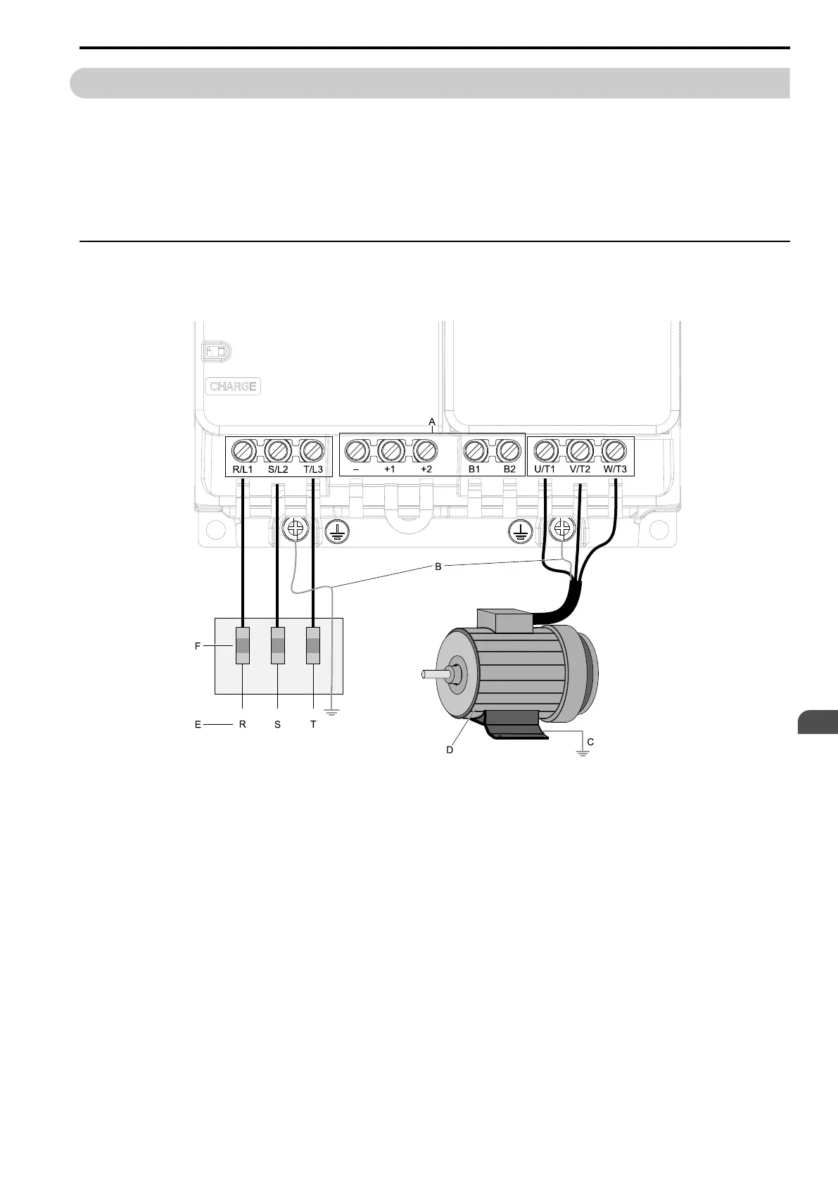
A - DC bus terminal
B - Connect to the drive ground
terminal.
C - Ground the motor case.
D - Three-Phase Motor
E - Use terminals R/L1, S/L2, and T/
L3 for three-phase power supply
input. Use terminals L/L1 and N/
L2 for single-phase power supply
input.
F - Input Protection (Fuses or Circuit
Breakers)
Note:
The locations of terminals are different for different drive models.
Figure 3.2 Wiring the Main Circuit and Motor