3.9 Braking Resistor Installation
86 SIEPCYEUOQ2V01A Q2V Technical Manual
3.9 Braking Resistor Installation
A braking resistor or braking resistor unit (dynamic braking option) helps stop the motor quickly and smoothly
when there is high load inertia.
If you try to decelerate a motor in less time than usual for a coast to stop, the motor will rotate faster than the
synchronous speed that aligns with the set frequency. This will cause the motor to become an induction generator.
The inertia energy of the motor and regenerate to the drive and charge the drive DC bus capacitor and increase the
voltage. If the voltage is more than the overvoltage level, an ov [Overvoltage] will occur. To prevent these
overvoltage faults, a dynamic braking option is necessary.
WARNING!
Set L3-04 = 0 [StallP@Decel Enable = Disabled] when you operate the drive with:
• a regenerative converter
• regenerative unit
• braking resistor
• braking resistor unit.
If you set the parameter incorrectly, the drive can decelerate for too long and cause serious injury or death.
NOTICE: Before you connect a dynamic braking option to the drive, make sure that qualified personnel read and obey the
Braking Unit and Braking Resistor Unit Installation Manual (TOBPC72060001). If you do not read and obey the manual or if
personnel are not qualified it can cause damage to the drive and braking circuit.
Note:
• Select the correct braking circuit size to dissipate the power that is necessary to decelerate the load in the correct time. Before you run
the drive, make sure that the braking circuit can dissipate the energy for the set deceleration time.
• To install a dynamic braking option, set L8-01 = 0 [3%ERF DBR Protection = Disabled].
WARNING! Fire Hazard. Do not connect a braking resistor to terminals +1 or -. Use terminals B1 and B2 for the braking resistor
connections. If you connect a braking resistor to the incorrect terminals, it can cause damage to the drive and braking circuit and
serious injury or death.
NOTICE: Connect braking resistors to the drive as shown in the connection diagram examples. If you wire the braking circuits
incorrectly, it can cause damage to the drive or equipment.
To connect a Yaskawa ERF series braking resistor to the drive, set L8-01 = 1 [Enabled].
To use a non-ERF-type braking resistor, connect a thermal overload relay between the drive and the braking
resistor and set a circuit to turn OFF the drive power at the trip contacts of the thermal overload relay.
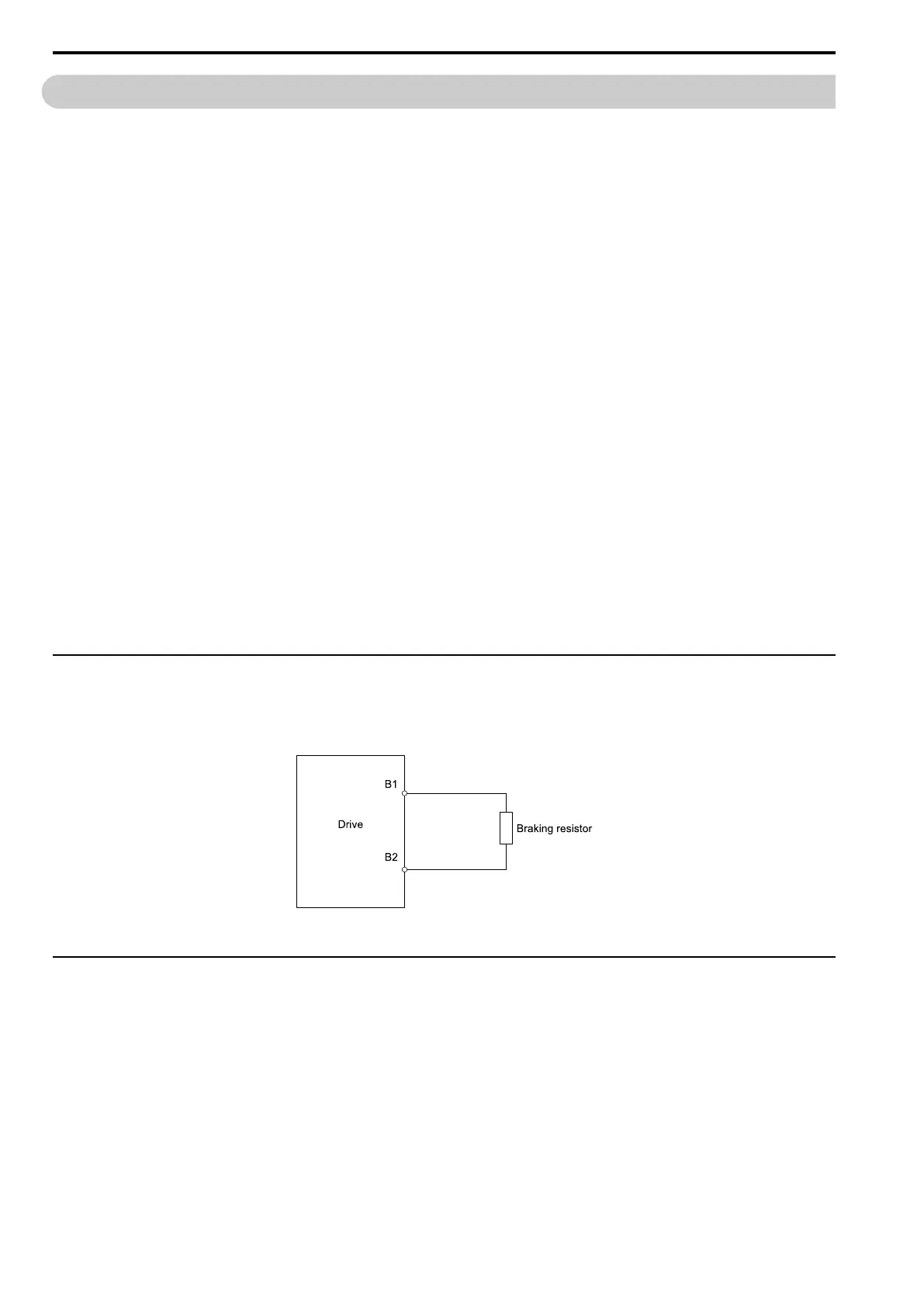
◆ Install a Braking Resistor: ERF-Type
Connect a braking resistor to drive models 2001 to 2021, B001 to B018, and 4001 to 4012. When you use a
braking resistor, set L8-01 = 1 [3%ERF DBR Protection = Enabled] and set one of the MFDO parameters H2-01
to H2-03 = 4C [MFDO Function Select = BrkRes Fault]. Use a sequence to turn OFF the power with a MFDO.
Figure 3.36 Install an ERF-Type Braking Resistor
◆ Install a Braking Resistor Unit: LKEB-Type
Connect the braking resistor unit as shown. To install a braking resistor unit, set L8-01 = 0 [3%ERF DBR
Protection = Disabled].
This product has a built-in braking transistor.
To prevent overheating the braking resistor unit, set a sequence to de-energize the drive at the trip contacts of the
thermal overload relay.

 Loading...


