3.5 Control Circuit Wiring
80 SIEPCYEUOQ2V01A Q2V Technical Manual
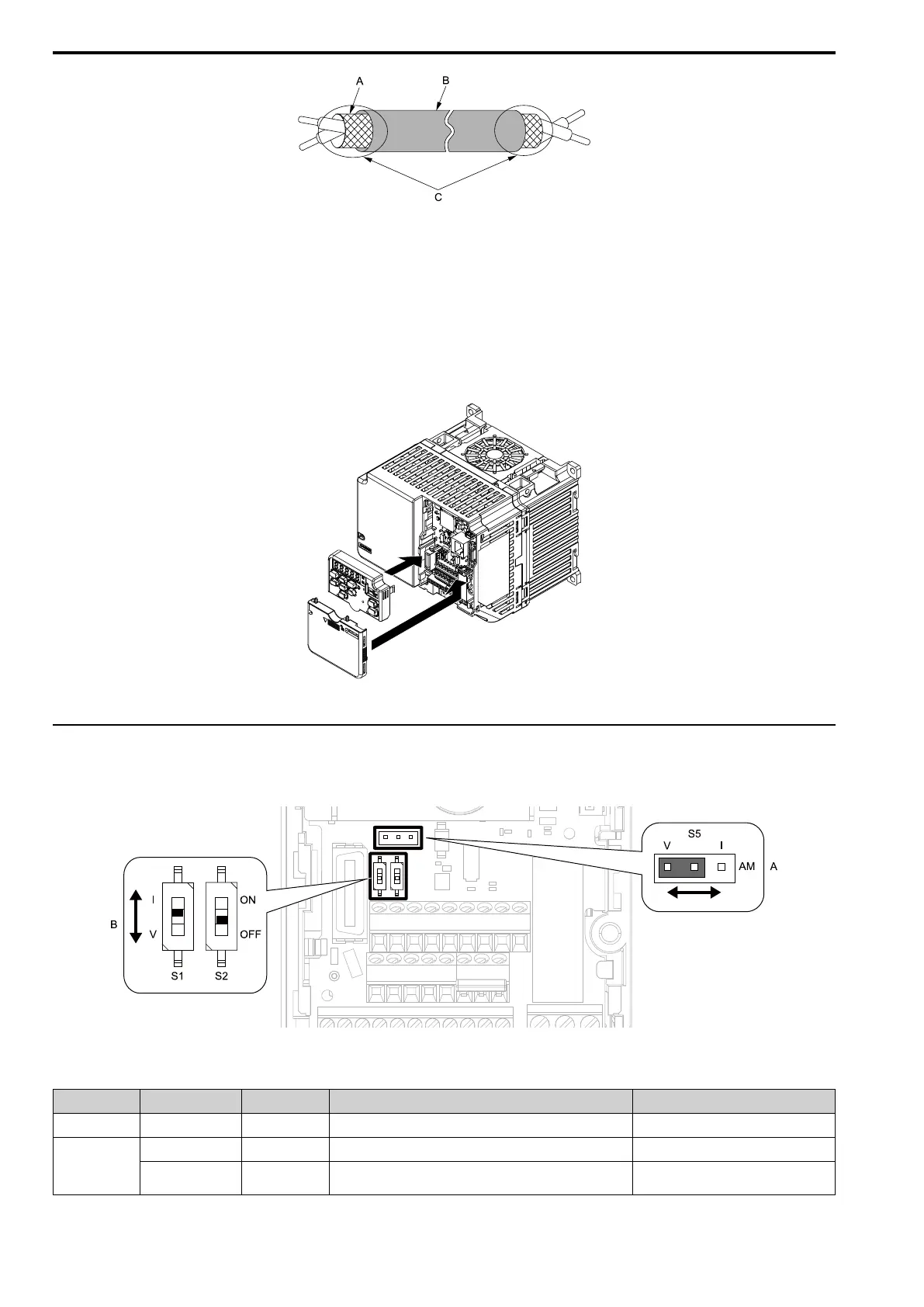
A - Connect the shield to terminal
GND of the drive.
B - Sheath
C - Insulate with electrical tape or
shrink tubing.
Figure 3.25 Prepare the Ends of Shielded Wire
3. Attach the front cover.
If you moved Jumper S5, attach the keypad before you attach the front cover.
If you did not move Jumper S5, attach the front cover.
Make sure that you do not pinch wires or signal lines between the front cover and the drive before you
reattach the cover.
Figure 3.26 Reattach the Front Cover
◆ Switches and Jumpers on the Terminal Board
The terminal board has switches to adapt the drive I/Os to the external control signals. Set the switches to select
the functions for each terminal.
Figure 3.27 Locations of Switches
Table 3.16 I/O Terminals and Switches Functions
Position Switch Terminal Function Default
A Jumper switch S5 AO Sets the output method for terminal AO (voltage or current). V (voltage output)
B
DIP switch S1 AI2 Sets the input method for terminal AI2 (voltage or current). I (current input)
DIP Switch S2 -
Enables and disables the Modbus communications termination
resistor.
OFF

 Loading...


