Electrical Installation
3
3.3 Main Circuit Wiring
SIEPCYEUOQ2V01A Q2V Technical Manual 67
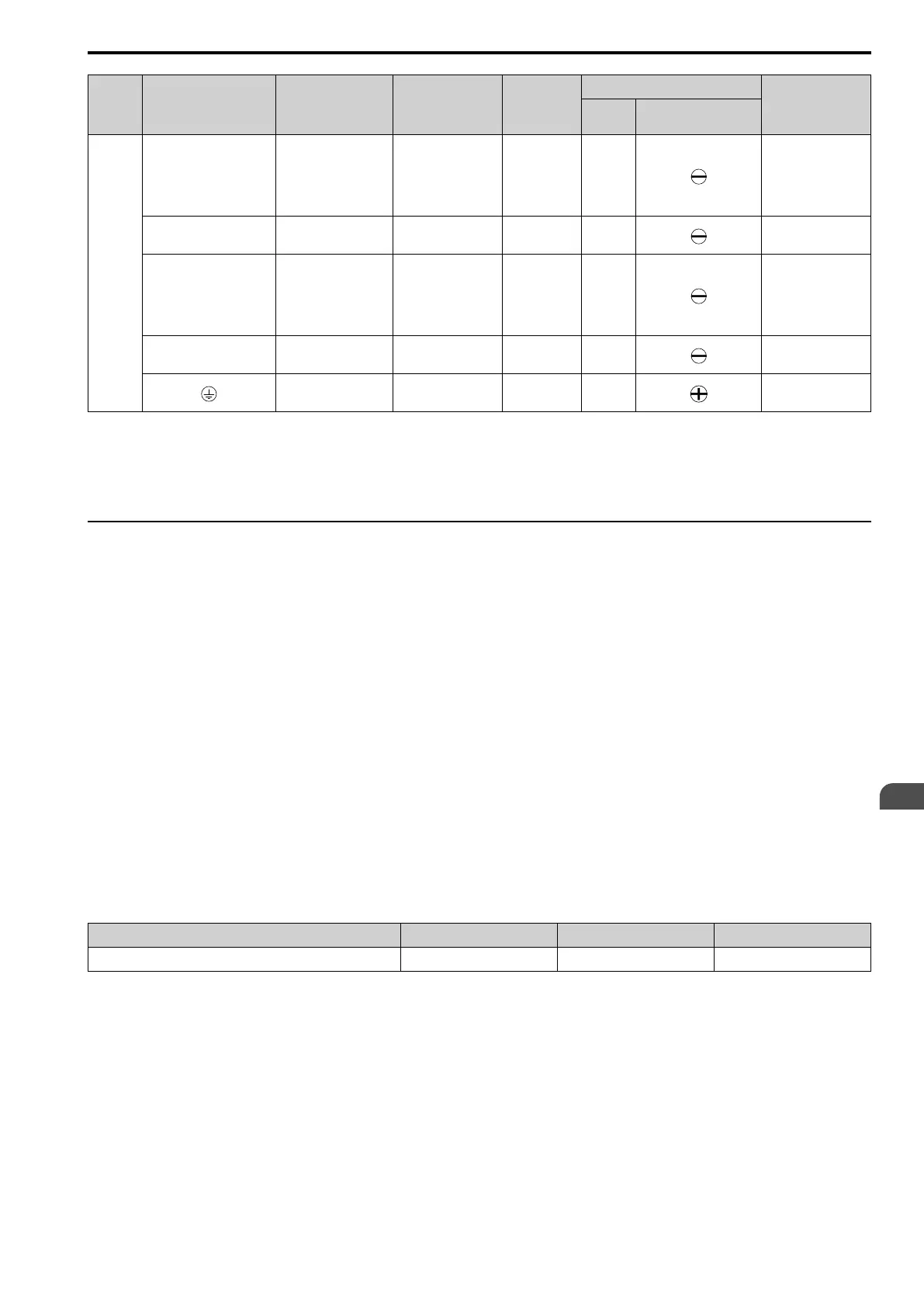
Model Terminal
Recommended
Gauge
mm
2
Applicable Gauge
mm
2
Wire
Stripping
Length
*1
mm
Terminal Screw
Tightening Torque
N∙m (in∙lb)
Size Shape
4060
R/L1, S/L2, T/L3 22 5.5 - 30 18 M5
• ≤ 22 mm
2
2.3 - 2.5
(19.8 - 22)
• 30 mm
2
≤
4.1 - 4.5
(36 - 40)
U/T1, V/T2, W/T3 14 5.5 - 22 18 M5
2.3 - 2.5
(19.8 - 22)
-, +1, +2 30 8 - 30 18 M5
• ≤ 22 mm
2
2.3 - 2.5
(19.8 - 22)
• 30 mm
2
≤
4.1 - 4.5
(36 - 40)
B1, B2 14 3.5 - 14 10 M4
1.5 - 1.7
(13.5 - 15)
8
*2
5.5 - 14 - M6
5.4 - 6.0
(47.8 - 53.1)
*1 Remove insulation from the ends of wires to expose the length of wire shown.
*2 If you turn on the built-in EMC filter, the leakage current of the drive will be more than 3.5 mA. Use these closed-loop crimp
terminals or equivalent to connect a protective ground wire that has a minimum cross-sectional area of 10 mm
2
(copper wire).
• 8-4NS from JST Mfg. Co., Ltd.
• R8-4S from NICHIFU Co.,Ltd.
◆ Main Circuit Terminal and Motor Wiring
This section outlines the various steps, precautions, and checkpoints for wiring the main circuit terminals and
motor terminals.
WARNING! Fire Hazard. Do not connect main power supply wiring to drive motor terminals U/T1, V/T2, and W/T3. Connect
main power supply wiring to main circuit input terminals R/L1, S/L2, and T/L3. Incorrect wiring can cause serious injury or death
from fire.
WARNING! Sudden Movement Hazard. Make sure that you align the phase order for the drive and motor when you connect the
motor to drive output terminals U/T1, V/T2, and W/T3. If the phase order is incorrect, it can cause the motor to run in reverse. If
the motor accidentally runs in reverse, it can cause serious injury or death.
NOTICE: Do not connect phase-advancing capacitors, LC/RC noise filters, or leakage breakers (RCM/RCD) to the motor
circuit. If you connect these devices to the output circuits, it can cause damage to the drive and connected equipment.
■ Cable Length Between Drive and Motor
When the wiring between the drive and the motor is too long, voltage drop along the motor cable can decrease
motor torque, usually at low frequency output. If you connect motors in parallel with long motor cable, this is also
a problem. Drive output current increases when the leakage current from the cable increases. An increase in
leakage current can cause overcurrent and decrease the precision of the current detection.
Use the values in Table 3.3 to adjust the drive carrier frequency. For systems that have 100 m (328 ft) or longer
motor wiring, if you use metal conduits or isolated cables for each phase, it will increase stray capacitance.
Table 3.3 Carrier Frequency against Cable Length Between Drive and Motor
Wiring Distance Between the Drive and Motor 50 m (164 ft) Maximum 100 m (328 ft) Maximum More than 100 m (328 ft)
Carrier Frequency 15 kHz or less 5 kHz or less 2 kHz or less
Note:
• To set the carrier frequency in a drive that is operating more than one motor, calculate the cable length as the total distance of wiring to
all connected motors.
• If the length of the wire between the drive and an induction motor is longer than 100 m (328 ft), set A1-02 = 0 [V/f Control].
• The maximum cable length between the drive and a PM motor is 100 m (328 ft).
• If the cable length between the drive and the motor is too long when A1-02 = 6 [PM AOLVector] or 8 [EZ Vector], change the setting
to A1-02 = 5 [PM OLVector].
• When you connect to a PM motor, it can be necessary to adjust the overcurrent detection. Refer to L8-27: OverCurr Det Gain on page
671 for more information.
■ Ground Wiring
Follow the precautions to wire the ground for one drive or a series of drives.

 Loading...


