12.7 H: TERMINALS
624 SIEPCYEUOQ2V01A Q2V Technical Manual
■ H5-22: Mbus SpdSrch Command
No.
(Hex.)
Name Description
Default
(Range)
H5-22
(11CF)
Mbus SpdSrch Command
Enables the Modbus communication register Speed Search function (bit0 of 15DFH).
0
(0, 1)
0 : Disabled
1 : Enabled
If you set H5-22 = 1 and H1-xx = 68 [SpdSrch Fref] at the same time, the drive will detect oPE03 [Multi-
Function Input Setting Err].
■ H5-25: Mbus 5A Reg1 Selection
No.
(Hex.)
Name Description
Default
(Range)
H5-25
(1589)
RUN
Mbus 5A Reg1 Selection
Returns the contents of the specified Modbus communications register when responding to the
master device.
0044H (U1-05)
(0000H - FFFFH)
■ H5-26: Mbus 5A Reg2 Selection
No.
(Hex.)
Name Description
Default
(Range)
H5-26
(158A)
RUN
Mbus 5A Reg2 Selection
Returns the contents of the specified Modbus communications register when responding to the
master device.
0045H (U1-06)
(0000H - FFFFH)
■ H5-27: Mbus 5A Reg3 Selection
No.
(Hex.)
Name Description
Default
(Range)
H5-27
(158B)
RUN
Mbus 5A Reg3 Selection
Returns the contents of the specified Modbus communications register when responding to the
master device.
0042H (U1-03)
(0000H - FFFFH)
■ H5-28: Mbus 5A Reg4 Selection
No.
(Hex.)
Name Description
Default
(Range)
H5-28
(158C)
RUN
Mbus 5A Reg4 Selection
Returns the contents of the specified Modbus communications register when responding to the
master device.
0049H (U1-10)
(0000H - FFFFH)
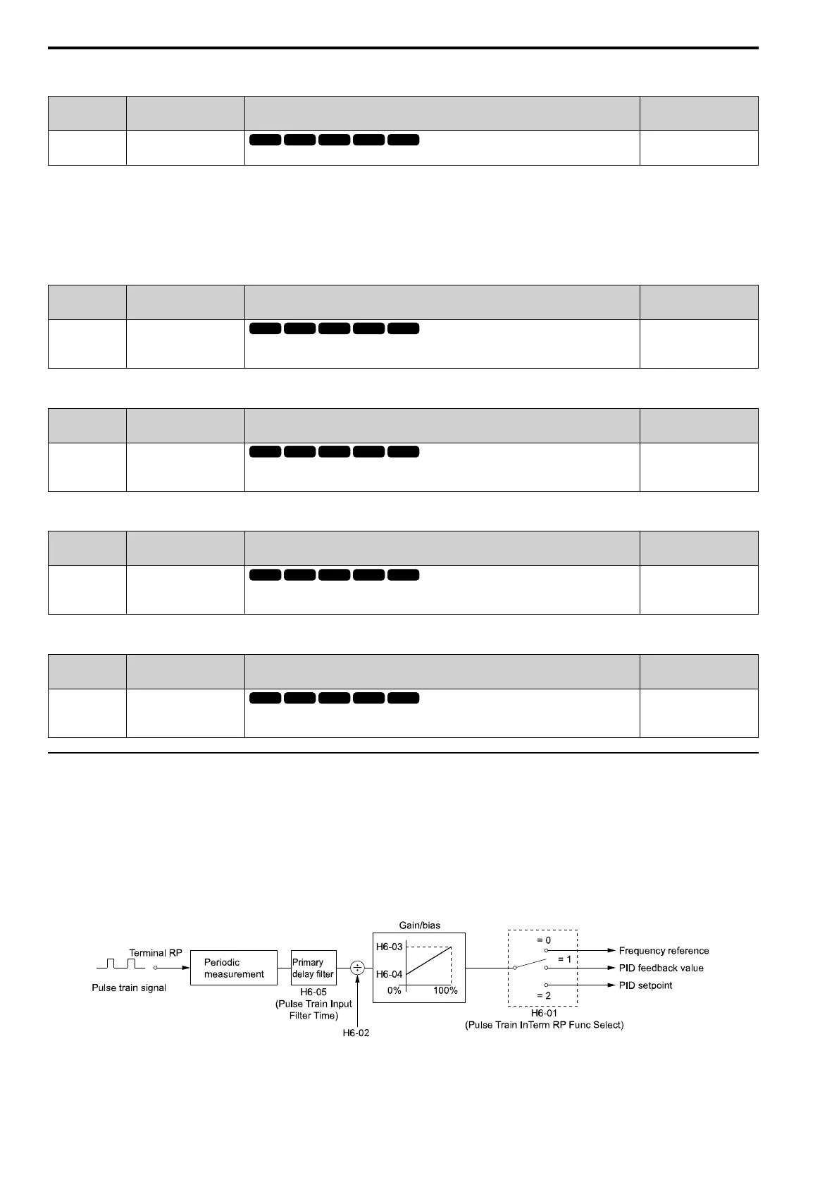
◆ H6: PULSE INPUT OUTPUT
H6 parameters set the drive pulse train input and pulse train monitor. These parameters select input and monitor
parameters and adjust the pulse train frequency.
A pulse train signal with a maximum single pulse of 32 kHz can be input to the drive input terminal PI. You can
use the pulse train signal as the frequency reference, PID feedback value, PID setpoint value, and speed feedback
for V/f Control mode.
A pulse train signal with a maximum frequency of 32 kHz can be output from the drive output terminal PO as the
monitor value. Sinking mode and sourcing mode are supported.
Figure 12.100 Pulse Train Input Block Diagram

 Loading...


