12.7 H: TERMINALS
566 SIEPCYEUOQ2V01A Q2V Technical Manual
12.7 H: TERMINALS
H parameters set functions for external input and output terminals.
◆ H1: DIGITAL INPUTS
H1 Parameters set the MFDI terminal functions.
■ H1-01 to H1-07 Terminal DI1 to DI7 Function Selection
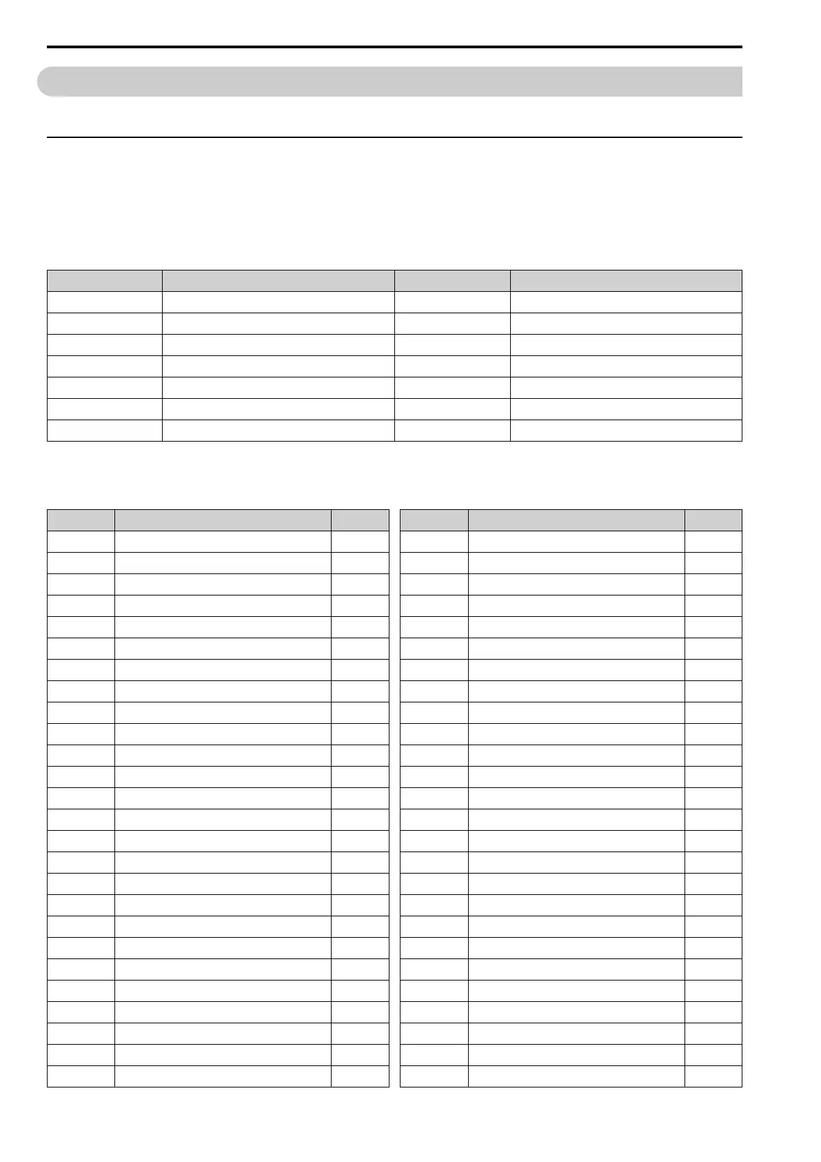
The drive has 7 MFDI terminals. These are the drive default settings and functions.
Table 12.37 MFDI Default Settings and Functions
No. Name Default Function
H1-01 DI1 Function Selection 1 (0)
*1
Forward Run
H1-02 DI2 Function Selection 2 (0)
*1
Reverse Run
H1-03 DI3 Function Selection 24 ExF NO-AlCoast
H1-04 DI4 Function Selection 7B Fault Reset
H1-05 DI5 Function Selection A (5)
*1
MultSpd Ref1
H1-06 DI6 Function Selection B (A)
*1
MultSpd Ref2
H1-07 DI7 Function Selection 6 (B)
*1
Jog Reference
*1 The value in parentheses identifies the default setting when you set A1-03 = 3330 [Init Parameters = 3-Wire Initialization].
Refer to Table 12.38 and use H1-xx [MFDI Function Select] to set the function.
Table 12.38 MFDI Setting Values
Setting Value Function Reference
0 Through Mode
569
1
*1
Forward RUN (2-Wire)
570
2
*1
Reverse RUN (2-Wire)
570
3
*1
Run Command (2-Wire Sequence 2)
570
4
*1
FWD/REV (2-Wire Sequence 2)
570
5
*1
3-Wire Sequence
571
6 Jog Reference Selection
571
7
*1
Forward Jog
572
8
*1
Reverse Jog
572
9 External Reference 1/2 Selection
572
A Multi-Step Speed Reference 1
572
B Multi-Step Speed Reference 2
572
C Multi-Step Speed Reference 3
573
D Multi-Step Speed Reference 4
573
E Add Offset Frequency 1 (d7-03)
573
F Add Offset Frequency 2 (d7-03)
573
10 Add Offset Frequency 3 (d7-03)
573
11 LOCAL/REMOTE Selection
573
12 Analog Terminal Enable Selection
574
15 Reverse Rotation Identifier
574
16 Reference Sample Hold
574
17 Accel/Decel Ramp Hold
574
18 Accel/Decel Time Selection 1
575
19 Accel/Decel Time Selection 2
575
1A Drive Enable
575
1B
*1
Baseblock Command (N.O.)
575
Setting Value Function Reference
1E
*1
Baseblock Command (N.C.)
576
20 to 2F
*1
External fault
576
30 DC Injection Braking Command
577
32 High Slip Braking (HSB)
577
34
*1
Fast Stop (N.O.)
577
35
*1
Fast Stop (N.C.)
577
3E
*1
Short Circuit Braking (N.O.)
578
3F
*1
Short Circuit Braking (N.C.)
578
40
*1
KEB Ride-Thru 1 Activate (N.C.)
578
41
*1
KEB Ride-Thru 1 Activate (N.O.)
579
42
*1
KEB Ride-Thru 2 Activate (N.C.)
579
43
*1
KEB Ride-Thru 2 Activate (N.O.)
579
44 Field Weakening
579
45 ASR Gain (C5-03) Select
579
46 ASR Integral Reset
580
60 Timer Function
580
61 Motor 2 Selection
580
62 Up Command
580
63 Down Command
582
65 Up 2 Command
582
66 Down 2 Command
584
67 Speed Search from Fmax
584
68 Speed Search from Fref
584
6A PID Disable
584
71 PID Integrator Reset
584
72 PID Integrator Hold
584

 Loading...


