Parameter Details
12
12.1 A: INITIALIZATION
SIEPCYEUOQ2V01A Q2V Technical Manual 437
Note:
• You must set A1-01 = 1 [Access Level = Manual Setup] to access parameters A2-01 to A2-32.
• When A1-07 = 1 or 2 [Q2pack Enable = Enable Q2pack or With DI], the drive saves qx-xx [q1-01 to q8-40: Q2pack Parameters] to
A2-01 to A2-32.
The drive saves these parameters to A2-01 to A2-32.
• The drive saves a maximum of 32 parameters.
Note:
Set A1-01 = 2 [Standard Parameters] or A1-01 = 3 [Expert Parameters] to save the necessary parameters.
• The drive automatically saves changed parameters to A2-17 to A2-32.
Note:
Set A2-33 = 1 [Manual Autoset Parameters = Auto Save].
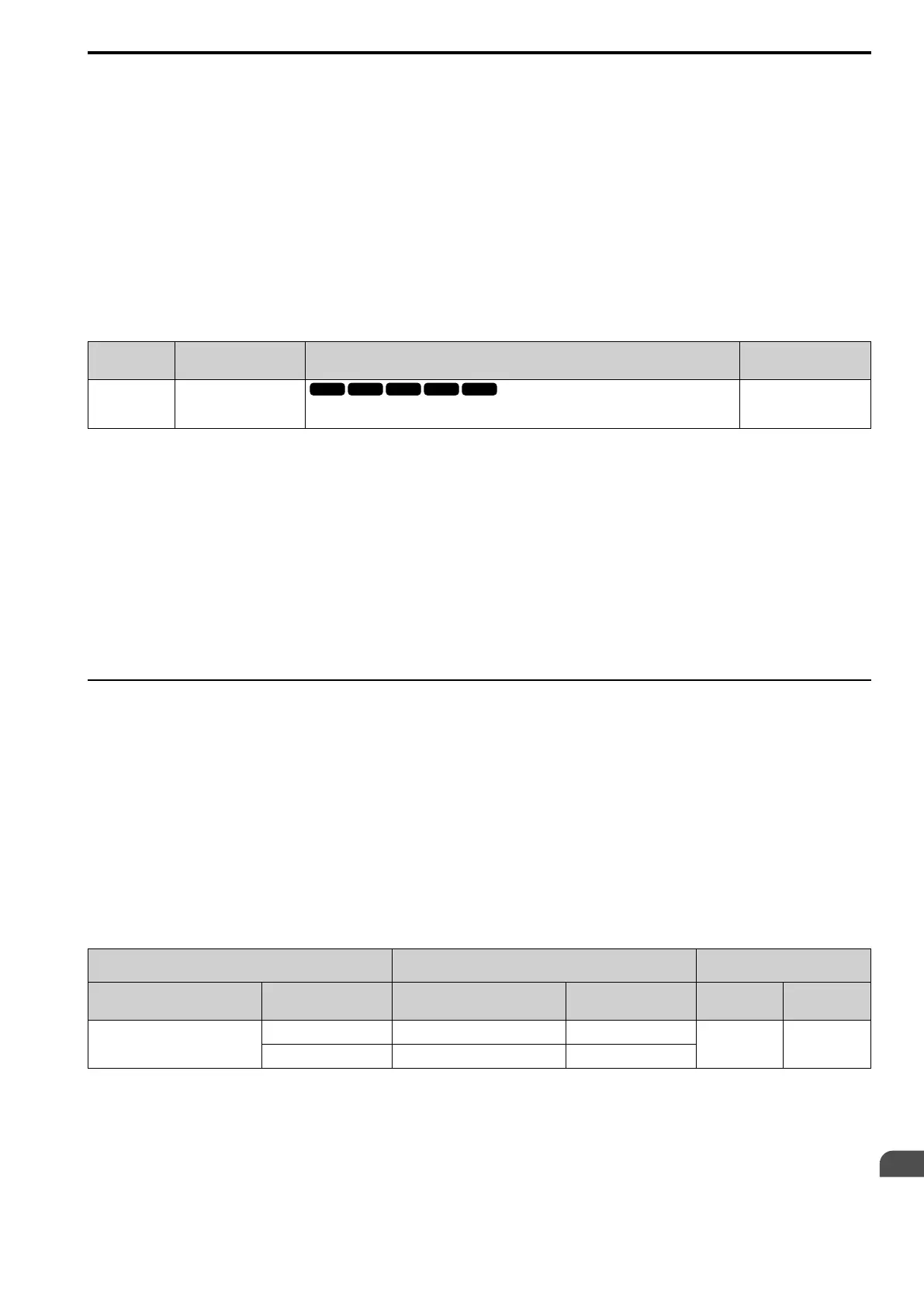
■ A2-33: Manual Autoset Parameters
No.
(Hex.)
Name Description
Default
(Range)
A2-33
(0126)
Manual Autoset Parameters
Sets the automatic save feature for changes to parameters A2-17 to A2-32 [MAN2 Param7 to
MAN3 Param12].
0
(0, 1)
0 : Manual Entry
Set User Parameters manually.
1 : Auto Save
The drive automatically registers changed parameter A2-17 to A2-32. The drive automatically saves the most
recently changed parameter to A2-17, and saves a maximum of 16 parameters. After the drive registers 16
parameters, when you save a new parameter, the drive will remove a parameter from the User Parameter list to
make space for the new parameter. The drive removes parameters with First In, First Out.
Use Setup Mode to show the saved parameters.
Note:
In General-Purpose Setup Mode, the drive saves parameters starting with A2-27 because the drive saves parameters A2-26 and lower by
default.
◆ Notes for Elevator Applications
When using the drive for elevator applications, read the safety descriptions and precautions, and safely and
correctly use the device.
■ Conditions to Open and Close the Brake
Set L4-07 = 1 [SpAgree Det.Selection = No Detect@BB] to open and close the holding brake.
When L4-07 = 2 [Always Detect], the output frequency increases when you input the Run command although the
external baseblock command is input. Because of this, speed detection operates and will open the brake signal.
• Set Related Parameters
This table shows examples of parameter settings to use the terminal DO2-O2C as the holding brake open and
close signal.
Table 12.3 Holding Brake Open and Close Signal Setting Example
Brake Open and Close Signal Brake Open and Close Level Adjust
Applicable Control Methods
(A1-02 Settings)
Signal Name Parameter Settings Signal Name Parameter Settings
V/f Control
(0)
OLVector
(2)
Frequency (FOUT) Detection 2
L4-07 = 0 SpAgree Det.Level L4-01 = 1.0 Hz to 3.0 Hz
*1
x x
H2-03 = 5 SpAgree Det.Width L4-02 = 0.0 Hz to 0.5 Hz
*1 When A1-02 = 2 [OLVector], it is the usual setting range. When A1-02 = 0 [V/f Control], set L4-01 to the rated slip frequency of the
motor + approximately 0.5 Hz. If you set the value too low, motor torque will not be sufficient and it will cause motor rollback. Set
the parameter to agree with these conditions at the same time. If you set the value too high, it will cause overshoot at start.
• L4-01 > E1-09 [Min Output Frequency]
• L4-01 > L4-02 [Powloss Ramp Time@recovery]
*2 Use L4-02 to adjust the detection width of Frequency Detection 2. If rollback occurs when the motor stops, change the frequency to
approximately 0.1 Hz.

 Loading...


