12.1 A: INITIALIZATION
438 SIEPCYEUOQ2V01A Q2V Technical Manual
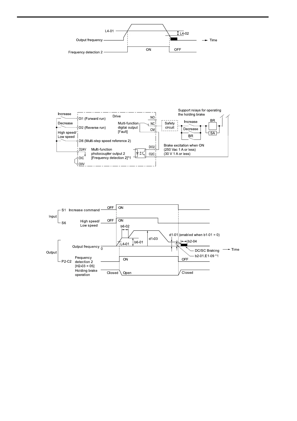
Figure 12.1 Frequency Detection 2
■ Sequence Circuit Configuration
Use these conditions to set the circuit for the open/close sequence of the holding brake:
• Set the sequence-side operation conditions to activate terminal DO2-O2C and open the holding brake.
• Set the sequence to close the holding brake in an emergency if the drive detects a fault.
• Set the sequence to open the holding brake when you enter an increase or decrease command.
Figure 12.2 Sequence Circuit Configuration Diagram
*1 L4-07 = 1 [SpAgree Det.Selection = No Detect@BB]
■ Time Chart
This figure shows the open and close sequence of the holding brake.
Figure 12.3 Holding Brake Open and Close Sequence Time Chart (V/f, OLV)
*1 Start braking from the higher set frequency between b2-01 [ZSpd/DCI Threshold] or E1-09 [Min Output Frequency].

 Loading...


