3.4 Main Circuit Terminal Block Wiring Procedure
72 SIEPCYEUOQ2V01A Q2V Technical Manual
A - Cable clamp
Figure 3.17 Strain Relief Example
Table 3.4 Recommended Wiring Tools
Screw
Size
Screw Shape Wire Gauge Adapter
Bit Model
(Manufacturer)
Torque Driver Model
(Tightening Torque)
Torque Wrench
(Tightening Torque)
M3 - Bit
SF-BIT-SL 0,5X3,0-70
(PHOENIX CONTACT)
TSD-M 1,2NM
(0.3 - 1.2 N∙m
(2.7 - 10.6 in∙lb))
-
M4 - Bit
SF-BIT-SL 1,0X4,0-70
(PHOENIX CONTACT)
TSD-M 3NM
(1.2 - 3.0 N∙m
(10.6 - 26.6 in∙lb))
-
M5
*1
≤ 25 mm
2
(AWG 10)
Bit
SF-BIT-SL 1,2X6,5-70
(PHOENIX CONTACT)
TSD-M 3NM
(1.2 - 3.0 N∙m
(10.6 - 26.6 in∙lb))
-
≥ 30 mm
2
(AWG 8)
-
4.1 - 4.5 N∙m
(36.3 - 39.8 in∙lb)
*2 *3
M6
(WAF: 5 mm)
- Bit
SF-BIT-HEX 5-50
(PHOENIX CONTACT)
-
5 - 9 N∙m
(44.3 - 79.7 in∙lb)
*2 *3
*1 When you wire drive models 2042, 2056, 4031, 4038, 4044, and 4060, select the correct tools for the wire gauge.
*2 Use 6.35 mm (0.25 in) bit socket holder.
*3 Use a torque wrench that can apply this torque measurement range.
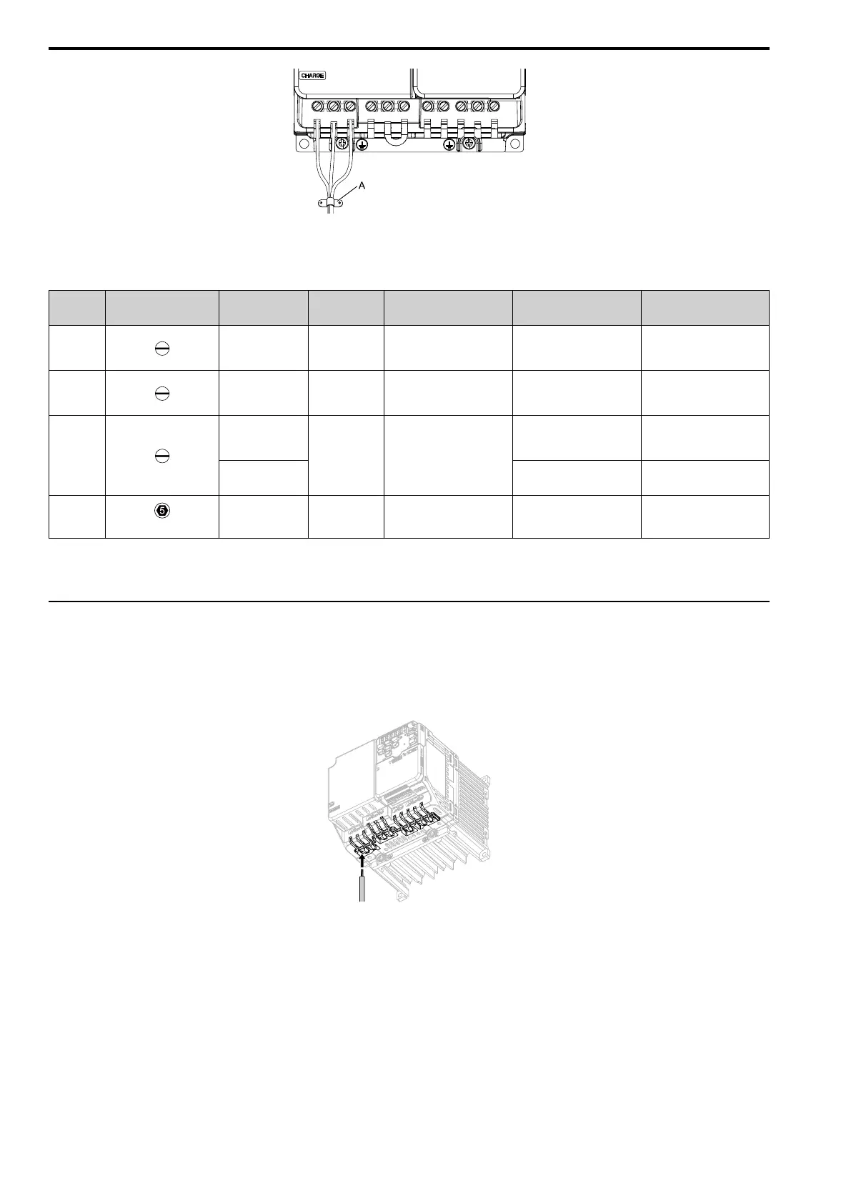
◆ Main Circuit Terminal Block Wiring Procedure
When terminals R/L1, S/L2, T/L3, -, +1, and +2 have IP20 protection covers, remove them.
1. Put a wire with prepared ends into the main circuit terminal block.
Look through the opening in the drive case to make sure that you correctly installed the wires into the
terminal block.
Figure 3.18 Install the Electrical Wire
Note:
There is a jumper between terminals +1 and +2. Remove the jumper, then wire to terminals +1 and +2.