3.6 Control I/O Connections
82 SIEPCYEUOQ2V01A Q2V Technical Manual
A - Load Impedance
Figure 3.28 Wiring to Use Pulse Train Output in Sourcing Mode
• Use in sinking mode
The external power supply changes the voltage level of the pulse train output signal. Keep the voltage from an
external source between 10.8 Vdc to 16.5 Vdc. Adjust the load impedance to keep the current at 16 mA or
lower.
External Power Supply (V) Load Impedance (kΩ) Sinking current (mA)
10.8 Vdc to 16.5 Vdc 1.0 kΩ or more 16 mA maximum
A - External power supply
B - Load Impedance
C - Sinking current
Figure 3.29 Wiring to Use Pulse Train Output in Sinking Mode
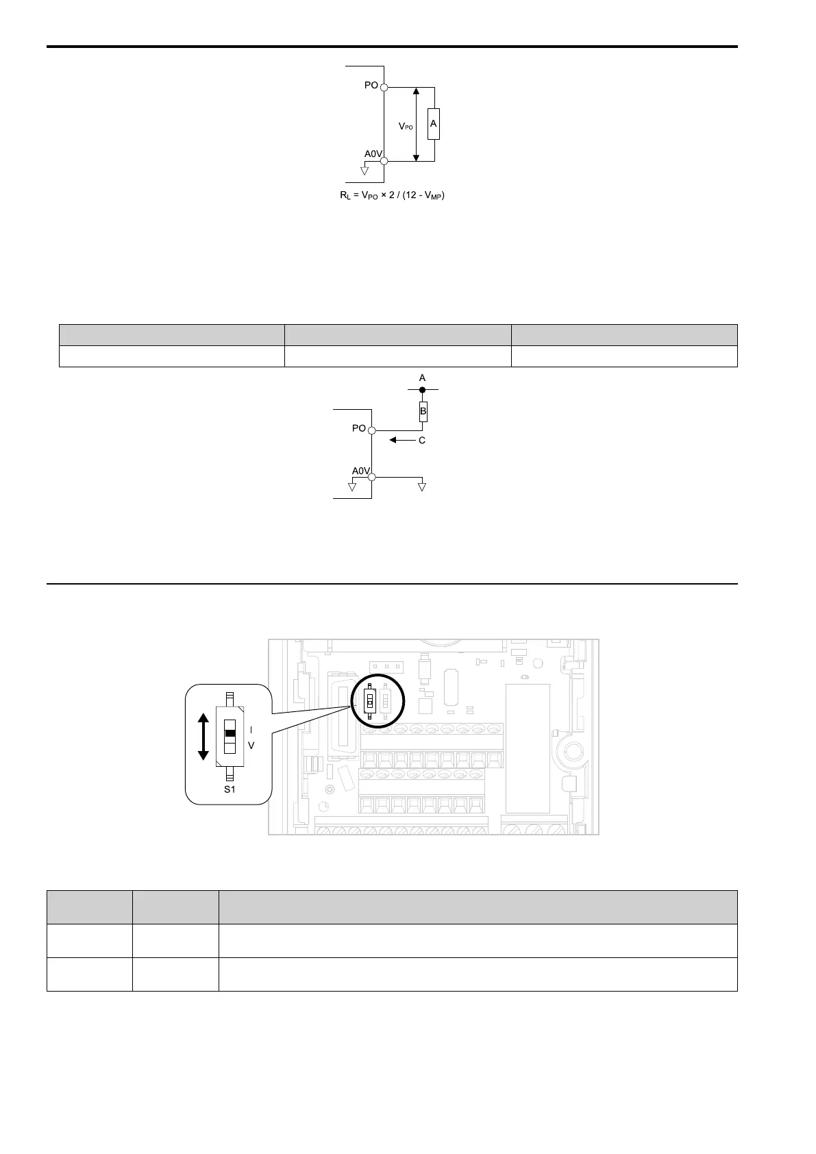
◆ Set the Input Signal for the MFAI Terminal AI2
Use terminal AI2 to input a voltage or a current signal.
Figure 3.30 Location of DIP Switch S1
Table 3.17 MFAI Terminal AI2 Signal Settings
Input Signal
DIP Switch S1
Settings
Parameter
Signal Level
Current input
I
(Default)
H3-09 = 2: 4 mA to 20 mA/0% to 100% (input impedance: 250 Ω)
H3-09 = 3: 0 mA to 20 mA/0% to 100% (input impedance: 250 Ω)
Voltage input V
H3-09 = 0: 0 V to 10 V/0% to 100% (with zero limit) (input impedance: 20 kΩ)
H3-09 = 1: 0 V to 10 V/0% to 100% (without zero limit) (input impedance: 20 kΩ)
Note:
Use tweezers or a jig with a tip width of approximately 0.8 mm (0.03 in) to set DIP switches.

 Loading...


