Network Communications
6
6.3 Modbus Communications
SIEPCYEUOQ2V01A Q2V Technical Manual 199
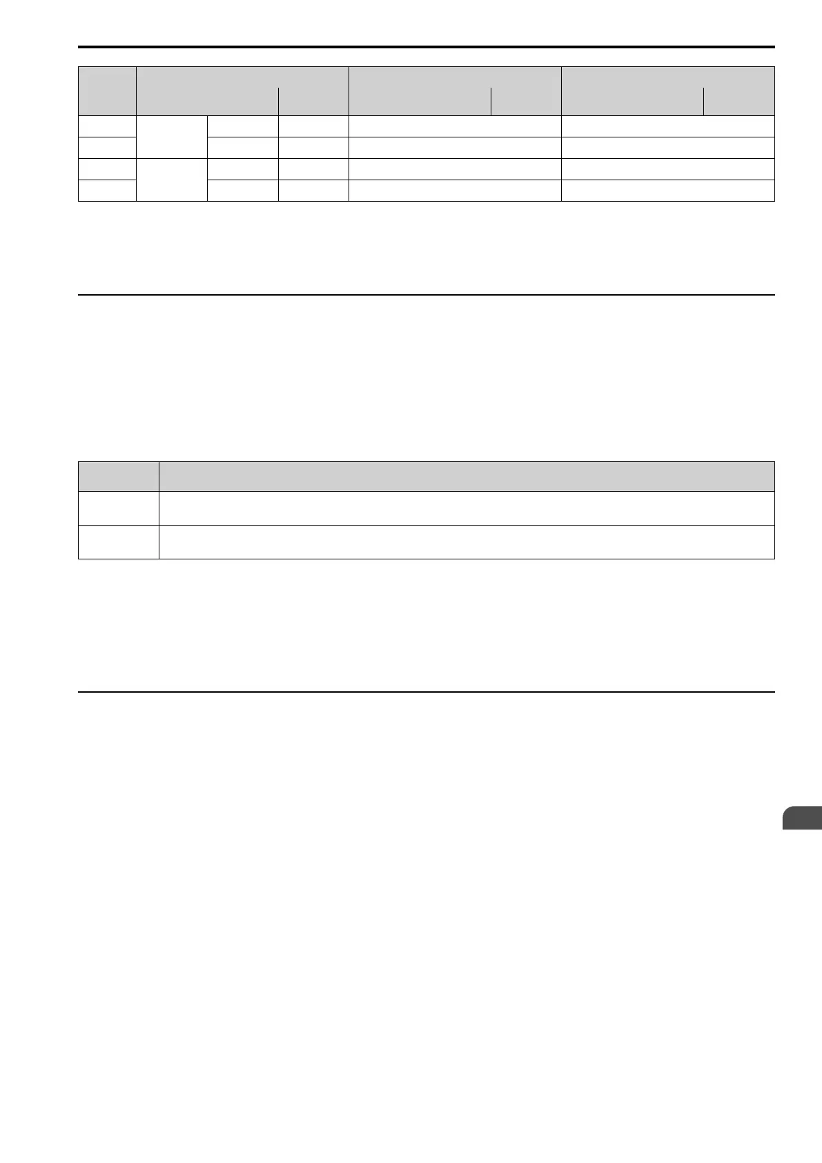
Byte
Command Message Response Message (When Normal) Response Message (When There is a Fault)
Setting Data
(Hex.)
Setting Data
(Hex.)
Setting Data
(Hex.)
14
Holding register
2 data
Upper 05 - -
15 Lower DC - -
16
CRC-16
Upper 55 - -
17 Lower 59 - -
Note:
The number of bytes set in the command message set the data quantity × 2 during the command message.
When you rewrite the parameter value with the write command through the H5-11 [Mbus ENTER Command
Mode] setting, you must use the Enter command to save and enable the contents of the changes.
◆ Enter Command
When you use Modbus communications to write parameters from the PLC to the drive, the H5-11 [Mbus ENTER
Command Mode] setting sets the function to enable these parameters from the Enter command. This section gives
information about the Enter command.
■ Types of Enter Commands
The drive supports the two Enter commands.
Table 6.9 Types of Enter Commands
Register No.
(Hex.)
Description
0900
When you write parameter data to the EEPROM, you will enable the data on the RAM at the same time.
This process saves the parameter changes until you de-energize the drive.
0910
This updates the data on the RAM, but does not write data to the EEPROM.
This process saves the parameter changes until you de-energize the drive.
Write 0 to register number 0900 or 0910 (Hex.) to enable the Enter command. You can only write to these
registers. If you read to these registers, it will cause an error.
Note:
• You can write the EEPROM to the drive a maximum of 100,000 times. Do not frequently execute the Enter command (0900 (Hex.))
that is written to EEPROM. The Enter command register is write-only. If this register is read, it will cause a Register Number Error (02
(Hex.)).
• When the command data or broadcast message is transmitted to the drive, the Enter command is not necessary.
◆ Self-Diagnostics
The drive can use Self-Diagnositcs to find the operation of the serial communications interface circuit. Self-
Diagnostics connects the transmission terminal to the reception terminal on the control circuit. It then transmits
the data sent by the drive and makes sure that the drive can communicate correctly.
1. Energize the drive.
2. Set H1-06 = 7F [DI6 Function Selection = Comms Test].
3. De-energize the drive.

 Loading...


