6.3 Modbus Communications
198 SIEPCYEUOQ2V01A Q2V Technical Manual
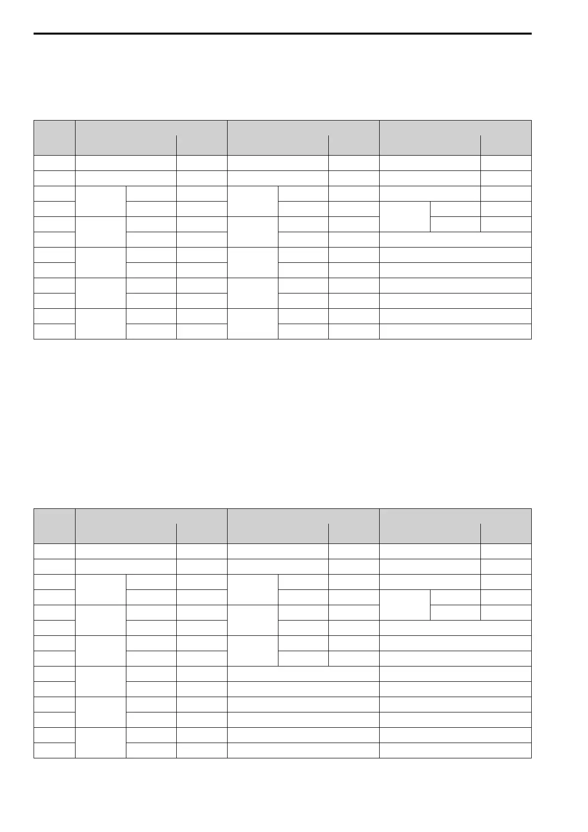
This table shows example messages when you read the frequency reference and torque limit from the drive for
slave 1, this register data is used for the examples:
• 0024H: U1-01 [Frequency Reference] = 60.00 Hz (6000 = 1770H)
• 0028H: U1-09 [Torque Reference] = 100.0% (1000 = 03E8H)
Table 6.7 Message Example When Reading the Contents of Non-Consecutive Holding Registers
Byte
Command Message Response Message (When Normal) Response Message (When There is a Fault)
Setting Data
(Hex.)
Setting Data
(Hex.)
Setting Data
(Hex.)
0 Slave address 01 Slave address 01 Slave address 01
1 Function code 67 Function code 67 Function code E7
2
Subfunction
code
Upper 01
Subfunction
code
Upper 01 Error code 02
3 Lower 0D Lower 0D
CRC-16
Upper EA
4
Data Quantity
Upper 00
Byte No.
Upper 00 Lower 31
5 Lower 02 Lower 04 -
6
Holding register
1 No.
Upper 00
Holding register
1 data
Upper 17 -
7 Lower 24 Lower 70 -
8
Holding register
2 No.
Upper 00
Holding register
2 data
Upper 03 -
9 Lower 28 Lower E8 -
10
CRC-16
Upper 8B
CRC-16
Upper 47 -
11 Lower 29 Lower ED -
Note:
The number of bytes set in the command message set the data quantity × 2 during the command message.
■ Writing to Non-Consecutive Holding Registers
The drive uses function code 67 (Hex.) and subfunction code 010E (Hex.) to read data with a maximum of 60
holding registers.
You must give the holding register number from which to write separately.
This table shows example messages when you write the frequency reference and torque limit from the drive for
slave 1, this register data os used for the examples:
• 0002H: Frequency Reference = 60.00 Hz (6000 = 1770H)
• 0004H: Torque Limit = 150.0% (1500 = 05DCH)
Table 6.8 Message Example When Writing to Non-Consecutive Holding Registers
Byte
Command Message Response Message (When Normal) Response Message (When There is a Fault)
Setting Data
(Hex.)
Setting Data
(Hex.)
Setting Data
(Hex.)
0 Slave address 01 Slave address 01 Slave address 01
1 Function code 67 Function code 67 Function code E7
2
Subfunction
code
Upper 01
Subfunction
code
Upper 01 Error code 02
3 Lower 0E Lower 0E
CRC-16
Upper EA
4
Data Quantity
Upper 00
Data Quantity
Upper 00 Lower 31
5 Lower 02 Lower 02 -
6
Byte No.
Upper 00
CRC-16
Upper D5 -
7 Lower 04 Lower FC -
8
Holding register
1 No.
Upper 00 - -
9 Lower 02 - -
10
Holding register
1 data
Upper 17 - -
11 Lower 70 - -
12
Holding register
2 No.
Upper 00 - -
13 Lower 04 - -

 Loading...


