Network Communications
6
6.3 Modbus Communications
SIEPCYEUOQ2V01A Q2V Technical Manual 197
– H5-25 = 0044H: U1-05 [Motor Speed] = 60.00 Hz (6000 = 1770H)
– H5-26 = 0045H: U1-06 [Output Voltage Ref] = 200.0 V (2000 = 07D0H)
– H5-27 = 0042H: U1-03 [Output Current] = 50% of drive rated current (100% = 8192, 50% = 4096 = 1000H)
– H5-28 = 0049H: U1-10 [In Terminal Status] = 00H
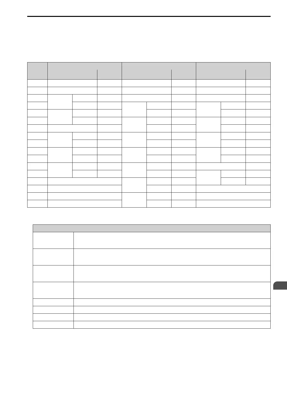
Table 6.6 Message Example When Reading from More than One Holding Register/Reading the Indicated Register
Byte
Command Message Response Message (When Normal) Response Message (When There is a Fault)
Setting Data
(Hex.)
Setting Data
(Hex.)
Setting Data
(Hex.)
0 Slave address 01 Slave address
01 Slave address 01
1 Function code 5A Function code
5A
Function code DA
2
Starting No.
Upper 00 Register status 0F Register status 0F
3 Lower 01
Data in holding
register 1
selected with
H5-25
Upper 17
Data in holding
register 1
selected with
H5-25
Upper 17
4
Data Quantity
Upper 00 Lower 70 Lower 70
5 Lower 02
Data in holding
register 2
selected with
H5-26
Upper 07
Data in holding
register 2
selected with
H5-26
Upper 07
6 Byte No. 04 Lower D0 Lower D0
7
First data
Upper 00
Data in holding
register 3
selected with
H5-27
Upper 10
Data in holding
register 3
selected with
H5-27
Upper 10
8 Lower 01 Lower 00 Lower 00
9
Next data
Upper 17
Data in holding
register 4
selected with
H5-28
Upper 00
Data in holding
register 4
selected with
H5-28
Upper 00
10 Lower 70 Lower 00 Lower 00
11
CRC-16
Upper 4F
Starting No.
Upper 00 Error code 02
12 Lower 43 Lower 01
CRC-16
Upper E9
13 -
Data Quantity
Upper 00 Lower 6C
14 - Lower 02 -
15 -
CRC-16
Upper AC -
16 - Lower D0
-
Note:
The number of bytes set in the command message set the data quantity × 2 during the command message.
Register status
bit 0 Data in register 1 selected with H5-25
1: Successfully read the register
0: Register read error
bit 1 Data in register 2 selected with H5-26
1: Successfully read the register
0: Register read error
bit 2 Data in register 3 selected with H5-27
1: Successfully read the register
0: Register read error
bit 3 Data in register 4 selected with H5-28
1: Successfully read the register
0: Register read error
bit 4 Not used
bit 5 Not used
bit 6 Not used
bit 7 Not used
When you rewrite the parameter value with the write command through the H5-11 [Mbus ENTER Command
Mode] setting, you must use the Enter command to save and enable the contents of the changes.
■ Reading the Contents of Non-Consecutive Holding Registers
The drive uses function code 67 (Hex.) and subfunction code 010D (Hex.) to read data with a maximum of 120
holding registers.
You must give the holding register number from which to read separately.

 Loading...


