3.3 Main Circuit Wiring
50 SIEPCYEUOQ2V01A Q2V Technical Manual
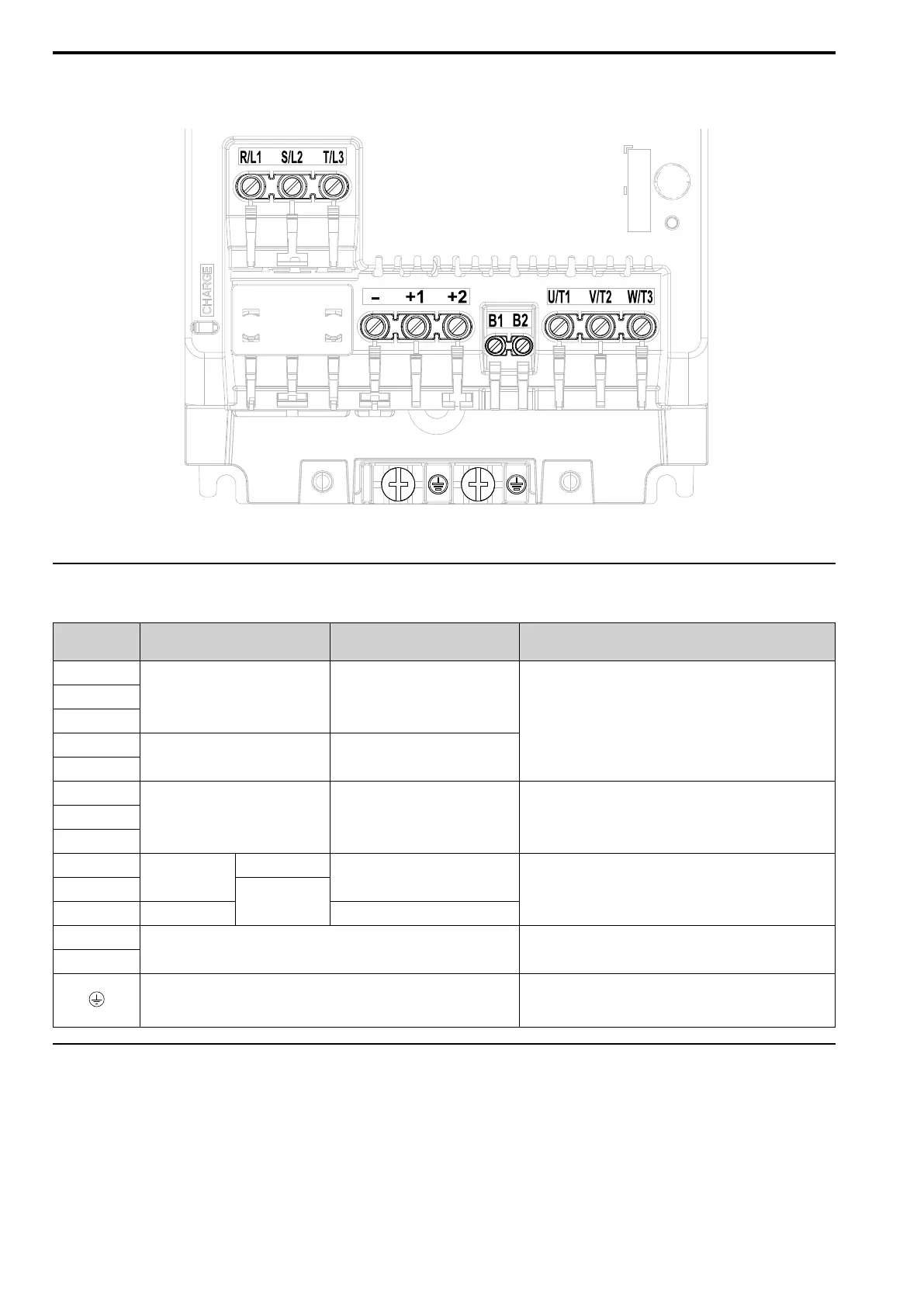
■ Models 4044, 4060
Figure 3.13 Three-Phase, With a Built-in EMC Filter
◆ Main Circuit Terminal Functions
Table 3.1 Main Circuit Terminal Names and Functions
Terminal
Models 2001 - 2082
Models 4001 - 4060
Models B001 - B018 Function
R/L1
Main circuit power supply input -
To connect a commercial power supply.
S/L2
T/L3
L/L1
- Main circuit power supply input
N/L2
U/T1
Drive output Drive output To connect a motor.V/T2
W/T3
-
DC power input
-
DC power input
+1 and +2: To connect a DC reactor.
Note:
Remove the jumper between terminals +1 and +2 to connect a DC
reactor.
+1
DC reactor
connection
+2 - -
B1
Braking resistor connection To connect a braking resistor or braking resistor unit.
B2
Ground Wiring
To ground the drive.
• 200 V: D class grounding (ground to 100 Ω or less)
• 400 V: C class grounding (ground to 10 Ω or less)
◆ Wire Selection
Select the correct wires for main circuit wiring.
Refer to Main Circuit Wire Gauges and Tightening Torques (CE-compliance) on page 149 for wire gauges and
tightening torques as specified by European standards.
Refer to Main Circuit Wire Gauges and Tightening Torques (UL Compliance) on page 167 for wire gauges and
tightening torques as specified by UL standards.
These tables use icons in Table 3.2 to show the shapes of the screw heads.

 Loading...


