Standards Compliance
5
5.2 European Standards
SIEPCYEUOQ2V01A Q2V Technical Manual 149
*1 Use terminals -, +1, +2, B1, and B2 to connect options to the drive.
WARNING! Fire Hazard. Only connect factory-recommended devices or circuits to drive terminals B1, B2, -, +1, +2, and
+3 terminals. Do not connect AC power to these terminals. Incorrect wiring can cause damage to the drive and serious
injury or death from fire.
*2 For circuit protection, the main circuit is separated from the surface case that can touch the main circuit.
*3 The control circuit is a Safety Extra-Low Voltage circuit. Separate this circuit from other circuits with reinforced insulation. Make
sure that the Safety Extra-Low Voltage circuit is connected as specified.
*4 Reinforced insulation separates the output terminals from other circuits. Users can also connect circuits that are not Safety Extra-Low
Voltage circuits if the drive output is 250 Vac 1 A maximum or 30 Vdc 1 A maximum.
*5 Set L8-05 = 1 [In PhaseLoss Selection = Enabled] or set the wiring sequence to prevent input phase loss.
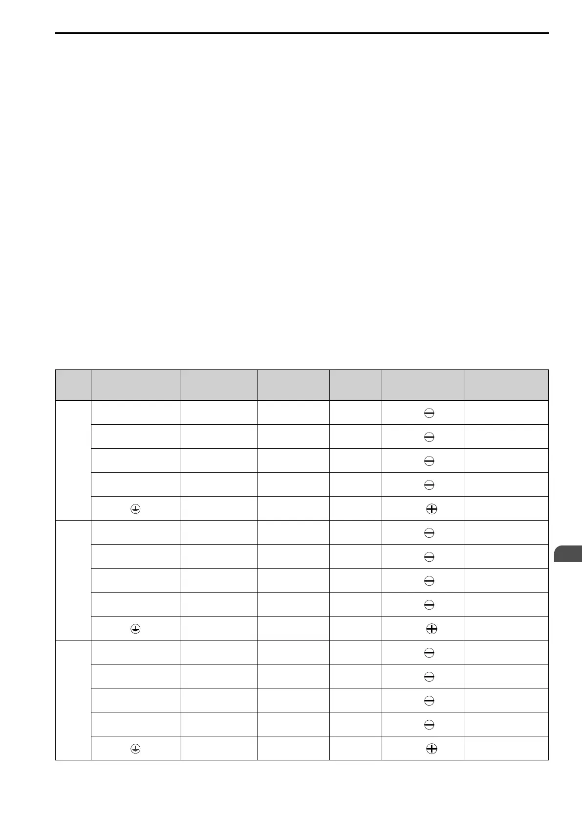
■ Main Circuit Wire Gauges and Tightening Torques (CE-compliance)
WARNING! Electrical Shock Hazard. Make sure that the protective ground wire complies with technical standards and local
safety regulations. The EN 61800-5-1: 2007 standard specifies that users must wire the power supply to automatically turn off
when the protective ground wire disconnects. If you turn on the internal EMC filter, the leakage current of the drive will be more
than 3.5 mA. You can also connect a protective ground wire that has a minimum cross-sectional area of 10 mm
2
(copper wire).
If you do not obey the standards and regulations, it can cause serious injury or death.
WARNING! Electrical Shock Hazard. Only connect peripheral options, for example a DC reactor or braking resistor, to terminals
+1, +2, -, B1, and B2. Failure to obey can cause serious injury or death.
Note:
• The recommended wire gauges are based on drive continuous current ratings with 75 °C (167 °F) 600 V class 2 heat-resistant indoor
PVC wire. Assume these conditions:
–Ambient temperature: 40 °C (104 °F) maximum
–Wiring distance: 100 m (3281 ft) maximum
–Normal Duty rated current value
• Refer to the instruction manual for each device for recommended wire gauges to connect peripheral devices or options to terminals +1,
+2, -, B1, and B2. Contact the manufacturer or your nearest sales representative if the recommended wire gauges for the peripheral
devices or options are out of the range of the applicable gauges for the drive.
Three-Phase 200 V Class (CE-compliance)
Model Terminal
Recommended Gauge
mm
2
Applicable Gauge
mm
2
Wire Stripping
Length
*1
mm
Terminal Screw
Tightening Torque
N∙m (in∙lb)
2001
R/L1, S/L2, T/L3 2.5 2.5 6.5
M3
0.5 - 0.6
(4.4 - 5.3)
U/T1, V/T2, W/T3 2.5 2.5 6.5
M3
0.5 - 0.6
(4.4 - 5.3)
-, +1, +2 2.5 2.5 6.5
M3
0.5 - 0.6
(4.4 - 5.3)
B1, B2 2.5 2.5 6.5
M3
0.5 - 0.6
(4.4 - 5.3)
2.5
*2
2.5
*2
-
M3.5
0.8 - 1.0
(7.1 - 8.9)
2002
R/L1, S/L2, T/L3 2.5 2.5 6.5
M3
0.5 - 0.6
(4.4 - 5.3)
U/T1, V/T2, W/T3 2.5 2.5 6.5
M3
0.5 - 0.6
(4.4 - 5.3)
-, +1, +2 2.5 2.5 6.5
M3
0.5 - 0.6
(4.4 - 5.3)
B1, B2 2.5 2.5 6.5
M3
0.5 - 0.6
(4.4 - 5.3)
2.5
*2
2.5
*2
-
M3.5
0.8 - 1.0
(7.1 - 8.9)
2004
R/L1, S/L2, T/L3 2.5 2.5 6.5
M3
0.5 - 0.6
(4.4 - 5.3)
U/T1, V/T2, W/T3 2.5 2.5 6.5
M3
0.5 - 0.6
(4.4 - 5.3)
-, +1, +2 2.5 2.5 6.5
M3
0.5 - 0.6
(4.4 - 5.3)
B1, B2 2.5 2.5 6.5
M3
0.5 - 0.6
(4.4 - 5.3)
2.5
*2
2.5
*2
-
M3.5
0.8 - 1.0
(7.1 - 8.9)

 Loading...


