Electrical Installation
3
3.8 External Interlock
SIEPCYEUOQ2V01A Q2V Technical Manual 85
3.8 External Interlock
For applications that will have unwanted effects on the system if the drive stops, make an interlock between
MFDO terminals set to H2-xx = 3 [MFDO Function Select = Fault] and H2-xx = 1 [Drive Ready].
◆ Drive Ready
When the drive is operating or is prepared to accept a Run command, the MFDO terminal to which Drive Ready
[H2-xx = 1] is set will enter the ON status.
In these conditions, Drive Ready is OFF and the drive ignores Run commands:
• The drive is de-energized
• During a fault
• There is problem with the control power supply
• There is a parameter setting error that will not let the drive run, although a Run command is entered
• An overvoltage or undervoltage fault occurs when the Run command is entered
• The drive is in Programming Mode.
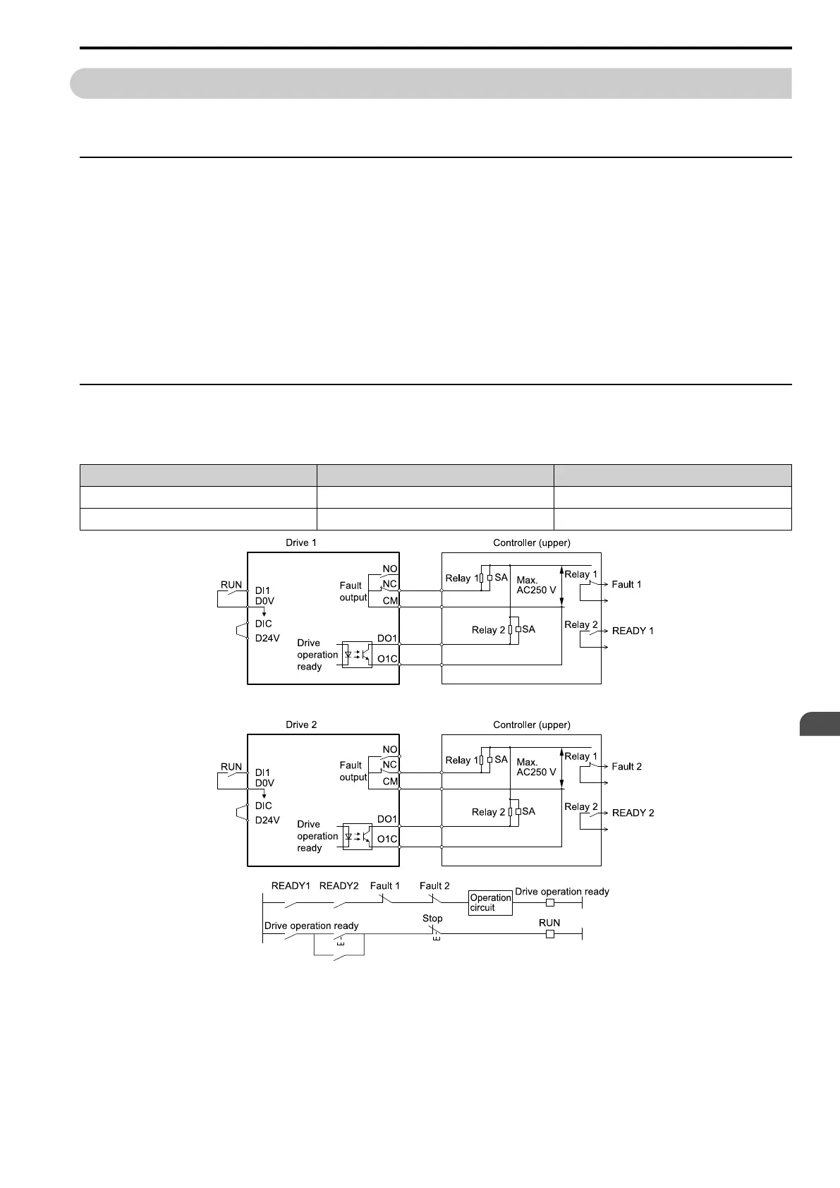
◆ Interlock Circuit Example
This is an example of how two drives that run one application use the Drive Ready and Fault output signals to
interlock with the controller.
Terminal Output Signal Parameter Settings for Output Signal
NO, NC, CM Fault H2-01 = 3
DO1-O1C Drive Ready H2-02 = 1
Figure 3.35 Interlock Circuit Example