7.10 Troubleshooting Without Fault Display
260 SIEPCYEUOQ2V01A Q2V Technical Manual
◆ The Motor Rotates in the Opposite Direction from the Run Command
Causes Possible Solutions
The phase wiring between the drive and motor is incorrect. • Examine the wiring between the drive and motor.
• Connect drive output terminals U/T1, V/T2, and W/T3 in the correct sequence to agree with
motor terminals U, V, and W.
• Switch two motor cables U, V, and W to reverse motor direction.
The forward direction for the motor is set incorrectly. • Connect drive output terminals U/T1, V/T2, and W/T3 in the correct sequence to agree with
motor terminals U, V, and W.
• Switch two motor cables U, V, and W to reverse motor direction.
A - For
ward
Rota
tion
Direc
tion
B - Load
Shaft
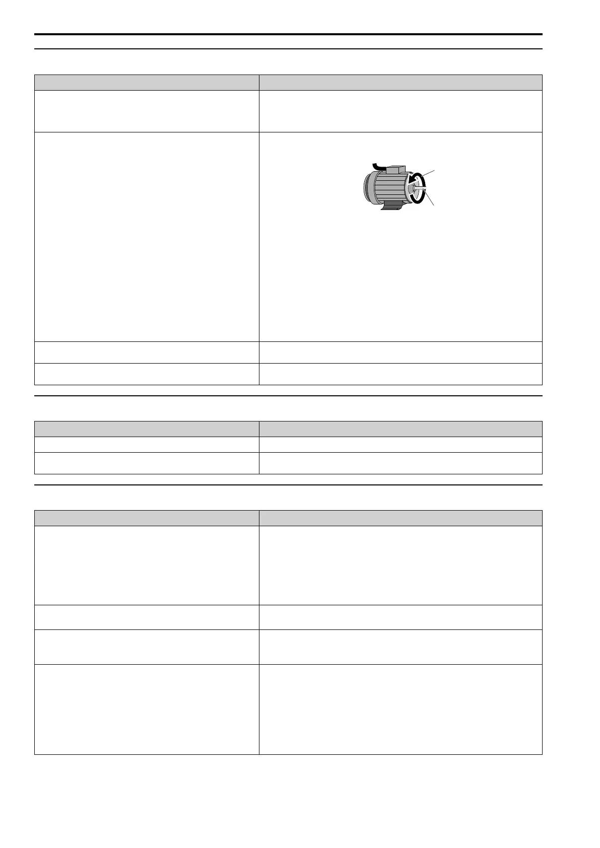
Figure 7.1 Forward Rotating Motor
Note:
• For Yaskawa motors, the forward direction is counterclockwise when looking from the
motor shaft side.
• Refer to the motor specifications, and make sure that the forward rotation direction is
correct for the application. The forward rotation direction of motors can be different for
different motor manufacturers and types.
The signal connections for forward run and reverse run on the drive control
circuit terminals and control panel side are incorrect.
Correctly wire the control circuit.
The motor is running at almost 0 Hz and the Speed Search estimated the
speed to be in the opposite direction.
Set b3-14 = 0 [Speed Bi-Directional Search = Disabled], then the drive will only do speed search
in the specified direction.
◆ The Motor Rotates in Only One Direction
Causes Possible Solutions
The drive will not let the motor rotate in reverse. Set b1-04 = 0 [Reverse Operation Selection = Enabled].
The drive did not receive a Reverse run signal and 3-Wire sequence is
selected.
Turn ON the terminals to which H1-xx = 5 [3-Wire Seq.] is set, and then enable reverse
operation.
◆ The Motor Is Too Hot
Causes Possible Solutions
The load is too heavy. • Decrease the load.
• Increase the acceleration and deceleration times.
• Examine the values set in L1-01 [Motor Cool Type for OL1 Calc], L1-02 [OL1 Protect Time],
and E2-01 [Mot Rated Current (FLA)].
• Use a larger motor.
Note:
The motor also has a short-term overload rating. Examine this rating carefully before setting
drive parameters.
The motor is running continuously at a very low speed. • Change the run speed.
• Use a drive-dedicated motor.
The drive is operating in a vector control mode, but Auto-Tuning has not
been done.
• Do Auto-Tuning.
• Calculate motor parameter and set motor parameters.
• Set A1-02 = 0 [Control Method = V/f Control].
The voltage insulation between motor phases is not sufficient. • Use a motor with a voltage tolerance that is higher than the maximum voltage surge.
• Use a drive-dedicated motor that is rated for use with AC drives for applications that use a
motor on drives rated higher than 400 V class.
• Install an AC reactor on the output side of the drive and set C6-02 = 1 [Carrier Frequency
Selection = 2.0 kHz].
Note:
When the motor is connected to the drive output terminals U/T1, V/T2, and W/T3, surges
occur between the drive switching and the motor coils. These surges can be three times the
drive input power supply voltage (600 V for a 200 V class drive, 1200 V for a 400 V class
drive).

 Loading...


