5.6 Safe Disable Input
184 SIEPCYEUOQ2V01A Q2V Technical Manual
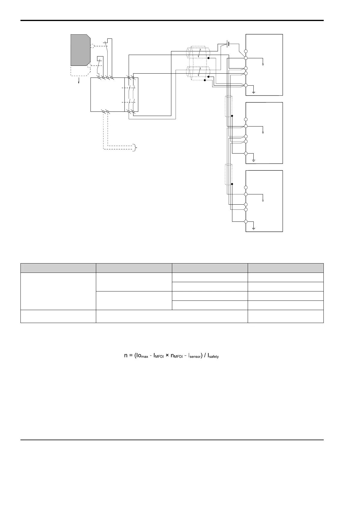
Figure 5.23 Connection Example to Use 24 V External Power Supply
■ Number of possible units to connect
Power Supply Digital Inputs 24 V Output Number of Drive Units
Internal power supply
(Drive 1)
Yes
(7-channel input)
Yes
*1
1
No 13
No
Yes
*1
4
No 17
External power supply -
Different for different external power
supply capacities
*2
*1 This is when you use a maximum of 150 mA.
*2 24 V, 12 mA is necessary for each drive.
Use this formula to calculate the number of units to connect:
• n: Number of units to connect
• Io
max
: Maximum current that the power supply can supply (234 mA for the internal power supply)
• I
MFDI
: Current consumed per MFDI (6 mA)
• n
MFDI
: Maximum number of MFDIs that can be activated at the same time (maximum of 7-channel)
• I
sensor
: Current externally supplied for sensor power supply (maximum of 150 mA)
• I
safety
: Current consumed by Safe Disable terminals H1 and H2 (12 mA)
Note:
Round the values to the first decimal place.
◆ Enabling and Disabling the Drive Output (“Safe Torque Off”)
This is an example of drive operation when as the drive changes from the "Safe Torque Off" status to usual
operation.
HC
Drive 1
D0V
H1
H2
GND
HC
Drive 2
D0V
H1
H2
GND
HC
Drive 3
D0V
H1
H2
GND
S1
S2
Open
Safety switch
Safety
controller
Reset/
feedback
input
Safety Electronic
Device Monitor output
Safe Disable input
Connect MFDO terminals set to
Safe Torque OFF [H2 - xx = E] in series.

 Loading...


