11.16 U: MONITORS
392 SIEPCYEUOQ2V01A Q2V Technical Manual
11.16 U: MONITORS
◆ U1: STATUS
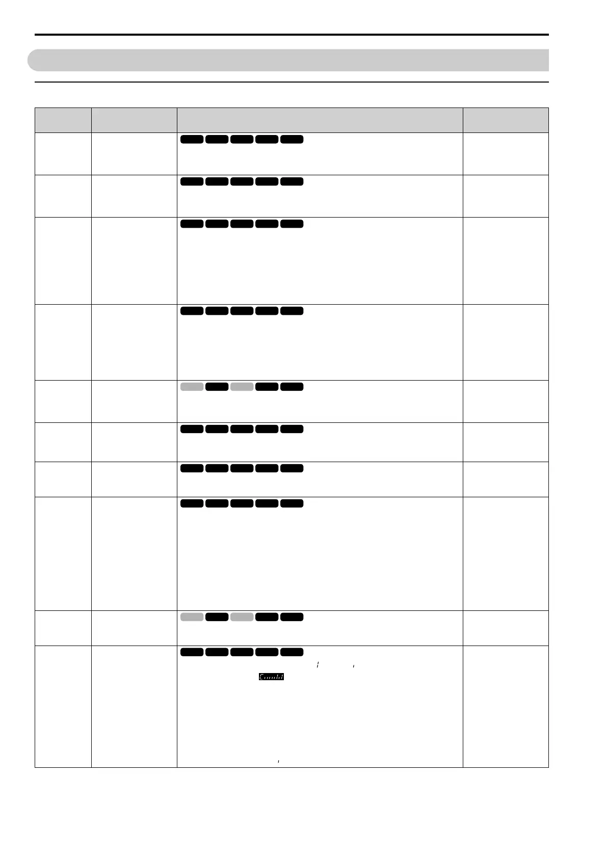
No.
(Hex.)
Name Description MFAO Signal Level
U1-01
(0040)
Frequency Reference
Shows the actual frequency reference value. Parameter o1-03 [FrqDisplay Unit Selection] sets the
display units.
Unit: 0.01 Hz
10 V = Maximum
frequency (-10 V to +10 V)
U1-02
(0041)
Output Frequency
Shows the actual output frequency. Parameter o1-03 [FrqDisplay Unit Selection] sets the display
units.
Unit: 0.01 Hz
10 V = Maximum
frequency (-10 V to +10 V)
U1-03
(0042)
Output Current
Shows the actual output current.
The keypad shows the value of U1-03 in amperes (A). When looking at the monitor through
Modbus communications, the current is “8192 = drive rated current (A)”. Calculate the current
from the monitor value that is in at Modbus communications using “Numerals being displayed /
8192 × drive rated current (A).
Unit: When the drive model changes, the display units for this parameter also change.
• 0.01 A units: 2001 to 2042, B001 to B018, 4001 to 4023
• 0.1A units: 2056 to 2082, 4031 to 4060
10 V = Drive rated current
U1-04
(0043)
Control Method
Shows the drive control method.
0 : V/f Control
2 : OLVector
5 : PM OLVector
6 : PM AOLVector
8 : EZ Vector
No signal output available
U1-05
(0044)
Motor Speed
Shows the actual detected motor speed. Parameter o1-03 [FrqDisplay Unit Selection] sets the
display units.
Unit: 0.01 Hz
10 V = Maximum
frequency (-10 V to +10 V)
U1-06
(0045)
Output Voltage Ref
Shows the output voltage reference.
Unit: 0.1 V
200 V class: 10 V = 200
Vrms
400 V class: 10 V = 400
Vrms
U1-07
(0046)
DC Bus Voltage
Shows the DC bus voltage.
Unit: 1 V
200 V class: 10 V = 400 V
400 V class: 10 V = 800 V
U1-08
(0047)
Output Power
Shows the internally-calculated output power.
Changing the setting of A1-02 [Control Method] also changes the signal level of the analog
output.
• A1-02 = 0: Drive capacity (kW)
• A1-02 = 2: Motor Rated Power (kW) [E2-11]
• A1-02 = 5, 6: PM Mot Rated Power (kW) [E5-02]
• A1-02 = 8: Motor Rated Power (kW) [E9-07]
Unit: When the drive model changes, the display units for this parameter also change.
• 0.01 A units: 2001 to 2042, B001 to B018, 4001 to 4023
• 0.1A units: 2056 to 2082, 4031 to 4060
10 V: Drive capacity (motor
rated power) kW
(-10 V to +10 V)
U1-09
(0048)
Torque Reference
Shows the internal torque reference value.
Unit: 0.1%
10 V = Motor rated torque
(-10 V to +10 V)
U1-10
(0049)
In Terminal Status
Shows the status of the MFDO terminal where = ON and = OFF.
For example, U1-10 shows when terminals DI1 and DI3 are ON.
bit0 : Terminal DI1 (MFDI 1)
bit1 : Terminal DI2 (MFDI 2)
bit2 : Terminal DI3 (MFDI 3)
bit3 : Terminal DI4 (MFDI 4)
bit4 : Terminal DI5 (MFDI 5)
bit5 : Terminal DI6 (MFDI 6)
bit6 : Terminal DI7 (MFDI 7)
bit7 : Not used (normal value of [ ]).
No signal output available

 Loading...


