Parameter List
11
11.16 U: MONITORS
SIEPCYEUOQ2V01A Q2V Technical Manual 393
No.
(Hex.)
Name Description MFAO Signal Level
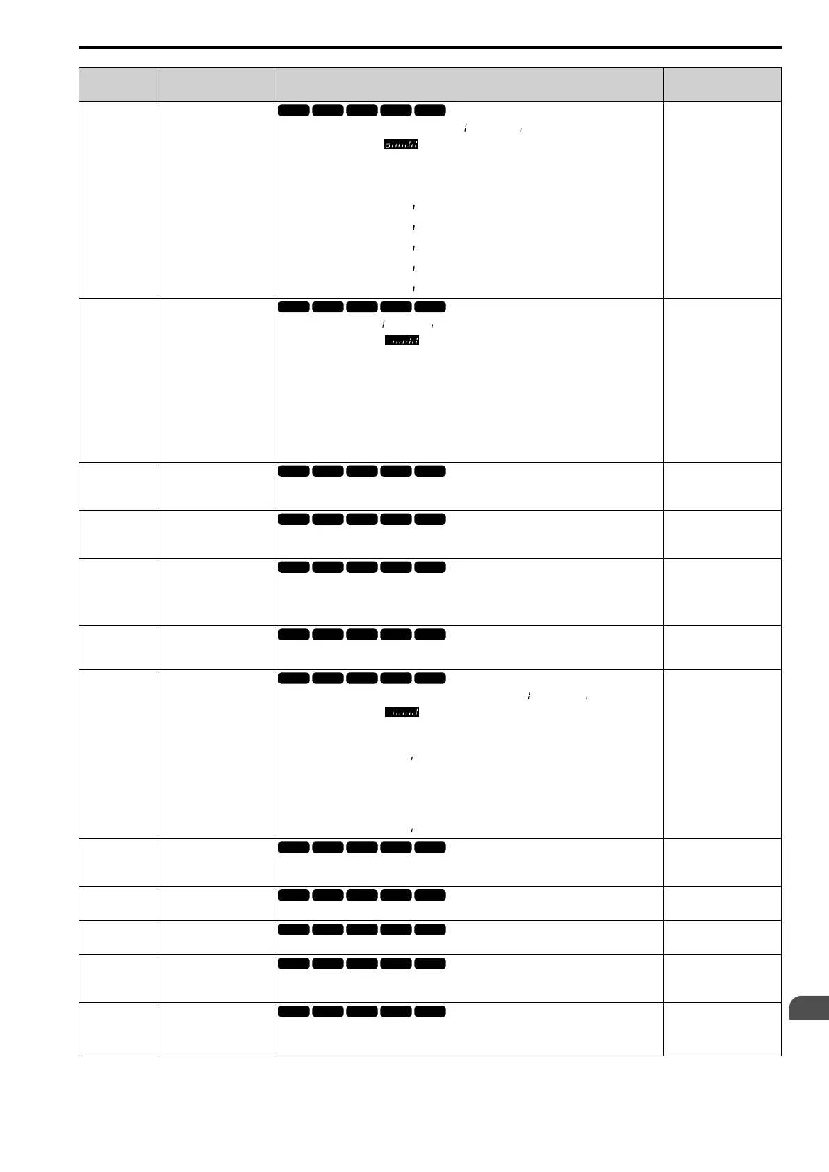
U1-11
(004A)
Out Terminal Status
Shows the status of the MFDO terminal where = (ON) and = (OFF).
For example, U1-11 shows when terminals NO and DO2 are ON.
bit0 : Terminal NO/NC-CM
bit1 : Terminal DO1-O1C
bit2 : Terminal DO2-O2C
bit3 : Not used (normal value of [ ]).
bit4 : Not used (normal value of [ ]).
bit5 : Not used (normal value of [ ]).
bit6 : Not used (normal value of [ ]).
bit7 : Not used (normal value of [ ]).
No signal output available
U1-12
(004B)
Drive Status
Shows drive status where = ON and = OFF.
For example, U1-12 shows during run with the Reverse Run command.
bit0 : During Run
bit1 : During zero-speed
bit2 : During reverse
bit3 : During fault reset signal input
bit4 : During speed agreement
bit5 : Drive Ready
bit6 : During minor fault detection
bit7 : During fault detection
No signal output available
U1-13
(004E)
Terminal AI1 InputLv
Shows the signal level of terminal AI1.
Unit: 0.1%
10 V = 100% (-10 V to +10
V)
U1-14
(004F)
Terminal AI2 InputLv
Shows the signal level of terminal AI2.
Unit: 0.1%
10 V = 100% (-10 V to +10
V)
U1-16
(0053)
SFS Output Frequency
Shows the output frequency after soft start. Shows the frequency with acceleration and
deceleration times and S-curves. Parameter o1-03 [FrqDisplay Unit Selection] sets the display
units.
Unit: 0.01 Hz
10 V = Maximum
frequency (-10 V to +10 V)
U1-18
(0061)
oPE Fault Parameter
Shows the parameter number that caused the oPE02 [Parameter Range Setting Error] or oPE08
[Parameter Selection Error].
No signal output available
U1-19
(0066)
Modbus Err.Code
Shows the contents of the Modbus communication error where =”error” and = “no error”.
For example, U1-19 shows when the drive detects a CRC error.
bit0 : CRC Error
bit1 : Data Length Error
bit2 : Not used (normal value of [ ]).
bit3 : Parity Error
bit4 : Overrun Error
bit5 : Framing Error
bit6 : Timed Out
bit7 : Not used (normal value of [ ]).
No signal output available
U1-24
(007D)
Input Pulse Monitor
Shows the frequency to pulse train input terminal PI.
Unit: 1 Hz
Determined by H6-02
U1-25
(004D)
SoftNumber Flash
Shows the ID.
No signal output available
U1-26
(005B)
SoftNumber ROM
Shows the ROM ID.
No signal output available
U1-50
(1199)
Expert
Virt. Analog Input
Shows the virtual analog input value.
Determined by H7-40
U1-91
(154E)
Expert
Output Voltage
Shows the drive internal output voltage reference.
Unit: 0.1 V
200 V class: 10 V = 200
Vrms
400 V class: 10 V = 400
Vrms

 Loading...


